Maytag MGC6536BDW Installation Manual - Page 7
Electrical Wiring Information
 |
View all Maytag MGC6536BDW manuals
Add to My Manuals
Save this manual to your list of manuals |
Page 7 highlights
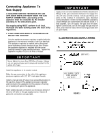
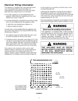
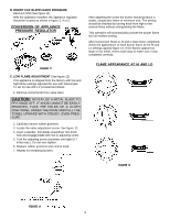
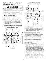
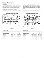
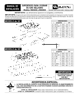
Electrical Wiring Information This appliance is equipped with a grounded type power cord. A grounded outlet must be provided. It is recommended, for convenience, the outlet be located (with reference to figure 6) as in A or B, below: A. If no other appliance is to be installed below this appliance: within either the shaded area or the cross hatched area shown in figure 6. B. If a Model MEW6500 or MEW5500 Series Electric Wall Oven is to be installed below this appliance, either: 1. within the cross hatched area of figure 6, or, 2. within an adjacent cabinet. If a wall oven is to be installed below this appliance and the counter units outlet is to be mounted within the cross hatched area of figure 6: 1. The cabinet's lower front panel, below the oven, must be made removable for access to the outlet. 2. A clearance hole for the power cord's plug (1-1/4² (3.18 cm) dia is recommended) must be provided through the oven's floor support shelf and, if necessary, through the slats supporting the shelf. The clearance hole should be located as near as practical to the rear of the shelf. If the outlet is to be mounted in either a left or right adjacent cabinet, a clearance hole, as described above, must be provided in the dividing wall between the cabinets. Figure 4; page 5, illustrates a typical (left side) dividing wall. The clearance hole (not shown in figure 4) can be located as is convenient in this left wall or in the corresponding right wall. In planning any installation, note that the free length of this appliance's power cord, extending beyond a point 3-3/4² (9.53 cm) left of the nominal center of the rear wall of the burner box, when viewed from the front of the unit, is approximately 46² (117 cm). User may experience occasional circuit tripping if Ground Fault Circuit Interrupter (GFCI) outlet or breaker is in use. Electrical Grounding Instructions This appliance is equipped with a (three-prong) grounding plug for your protection against shock hazard and should be plugged directly into a properly grounded receptacle. Do not cut or remove the grounding prong from this plug. THIS APPLIANCE MUST BE DISCONNECTED FROM ITS ELECTRICAL SUPPLY AT THE WALL RECEPTACLE BEFORE SERVICING THE APPLIANCE. 3 13/16² 9.7 cm 3 1/2² (8.89 cm) WIDE SLATS WHEN A WALL OVEN IS INSTALLED BELOW 30² MODEL CABINET BOTTOM FIGURE 6 7 29 3/8² 74.61 cm 37 3/16² 94.46 cm 4² MAX. 10.16 cm
-
 1
1 -
 2
2 -
 3
3 -
 4
4 -
 5
5 -
 6
6 -
 7
7 -
 8
8 -
 9
9 -
 10
10 -
 11
11 -
 12
12 -
13
-
14
-
15
-
16
-
17
-
18
-
19
-
20
-
21
-
22
-
23
-
24
-
25
-
26
-
27
-
28
-
29
-
30
-
31
-
32
-
33
 |
 |
