Maytag MGD5900TW Technical Education - Page 70
Timer Test, Motor Test, Supply Connections Test-Gas
 |
View all Maytag MGD5900TW manuals
Add to My Manuals
Save this manual to your list of manuals |
Page 70 highlights
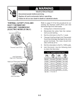
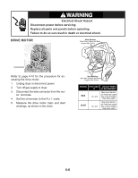
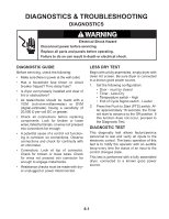
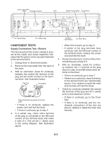
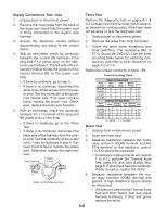
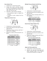
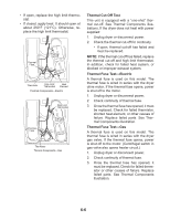
Supply Connections Test-Gas Timer Test 1. Unplug dryer or disconnect power. 2. Remove the cover plate from the back of the dryer and check that the power cord is firmly connected to the dryer's wire harness. Perform the diagnostic test on pages 6-1 & 6-2 to determine that the timer motor advances (should run continuously). If the timer does not advance or fails the diagnostic test: 1. Unplug dryer or disconnect power. 3. Access the electronic control without disconnecting any wiring to the control board. 4. With an ohmmeter, check for continuity between the neutral (N) terminal of the plug and P1-2 (white wire) on the electronic control board. The left side of the illustration below shows the position of the neutral terminal (N) on the power cord plug. • If there is continuity, go to step 5. • If there is no continuity, disconnect the white wire of the harness from the power cord. Test the continuity of the power cord neutral wire. If an open circuit is found, replace the power cord. Otherwise, replace the main wire harness. 5. With an ohmmeter, check the continuity between the L1 terminal of the plug and BK (black wire) on the timer. • If there is continuity, go to the Timer Test. • If there is no continuity, disconnect the black wire of the harness from the power cord. Test the continuity of the power cord L1 wire as illustrated in step 4. If an open circuit is found, replace the power cord. Otherwise, replace the main harness. Power Cord Plug L1 N COM G L1 N G Power cord terminals, gas dryer. 2. Remove the wires from timer terminals. 3. Check the timer motor resistance and timer switching. The resistance (BU to PT-1) should be 3 kΩ (±2). Use the timer encoding table below for switching conductivity, and refer to timer illustration on page 7-2 or 7-5. Reference contact continuity to timer - BK. Timer Encoding Table TIMED DRYING MODE Timer Timed Contacts Drying Cool Down Wrinkle Prevent Off W to BK O O O O R to BK X X O O V to BK O X X O BU to BK X X X O SENSOR DRYING MODE Timer Contacts Jeans Energy Preferred Less Dry Wrinkle Prevent Off W to BK X X O OO R to BK O O O OO V to BK X O O XO BU to BK X X X XO O = OPEN X = CLOSED Motor Test 1. Unplug dryer or disconnect power. 2. Open the dryer door. 3. Measure resistance between the motor relay common (COM) terminal and the P2-6 terminal on the electronic control. 1 to 6 Ω should be measured. • If resistance measurements are outside 1 to 6 Ω, perform the Thermal Fuse Test, page 6-6, and Door Switch Test, page 6-5; and check harness continuity. If they test good, replace the motor. 4. Measure resistance between the motor relay common (COM) terminal and ground. A high resistance (open) should be measured. • If it does not, perform the Thermal Fuse Test and Door Switch Test and check harness continuity. If they test good, replace the motor. 6-4
-
 1
1 -
2
-
3
-
4
-
5
-
6
-
7
-
8
-
9
-
10
-
11
-
12
-
13
-
14
-
15
-
16
-
17
-
18
-
19
-
20
-
21
-
22
-
23
-
24
-
25
-
26
-
27
-
28
-
29
-
30
-
31
-
32
-
33
-
34
-
35
-
36
-
37
-
38
-
39
-
40
-
41
-
42
-
43
-
44
-
45
-
46
-
47
-
48
-
49
-
50
-
51
-
52
-
53
-
54
-
55
-
56
-
57
-
58
-
59
-
60
-
61
-
62
-
63
-
64
-
 65
65 -
 66
66 -
 67
67 -
 68
68 -
 69
69 -
 70
70 -
 71
71 -
 72
72 -
 73
73 -
 74
74 -
 75
75 -
76
-
77
-
78
-
79
-
80
-
81
-
82
-
83
-
84
-
85
-
86
-
87
-
88
 |
 |
