Memorex MVDP1085-BLW Service Manual
Memorex MVDP1085-BLW - 8.4" - Widescreen Portable DVD Player Manual
 |
UPC - 749720014163
View all Memorex MVDP1085-BLW manuals
Add to My Manuals
Save this manual to your list of manuals |
Memorex MVDP1085-BLW manual content summary:
- Memorex MVDP1085-BLW | Service Manual - Page 1
MVDP1085-FLRP 8 TFT DISPLAY PORTABLE DVD PLAYER CONTENTS Page SPECIFICATIONS ...2 BLOCK DIAGRAM...3 DISASSEMBLY INSTRUCTIONS ...4 SAFETY CHECKS...5 TROUBLESHOOTING ...6 PRINTED CIRCUIT BOARDS ...8 WIRING DIAGRAM ...12 EXPLODED VIEW ...14 MECHANICAL PARTS LIST ...15 ELECTRICAL PARTS LIST ...17 IC - Memorex MVDP1085-BLW | Service Manual - Page 2
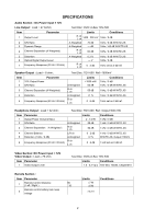
Section: DC Power input = 12V Video Output : Load = 75 ohm; Item Parameter 1 Video Output Level Test Disc: DVD=A-Bex TDV-540 Limits Conditions 1.0 ±0.2 Vp-p TDV-540, Title#3, Chapter#10 Remote Section : Item Parameter 1 Remote Control Distance ( Left / Right ) 2 Remote control battery task - Memorex MVDP1085-BLW | Service Manual - Page 3
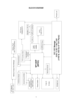
BLOCK DIAGRAM 3 AC Adaptor DC 12V / 1.5A Battery Charge Drive Manage Battery Pack (DC 7.4V 2500 mAh) DVD Door Switch Motor Driver D5954 DVD Mech. MG-9866H3H & HOP-1200X Power Switch TFT Panel Switch TFT Connect Boar Key Board (14 Key) TFT Panel PW080XU4 8" Speaker HP x 2 MT1389P (MPEG) Audio - Memorex MVDP1085-BLW | Service Manual - Page 4
DISASSEMBLY INSTRUCTIONS Top view of battery pack Bottom view of main unit B C A B Bottom view of battery pack B B A Disassembling Cabinet : Undo A, B, C screws as indicated Install / Detach the battery pack Follow the illustrations to install the battery pack. Press the release button at the - Memorex MVDP1085-BLW | Service Manual - Page 5
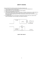
following safety checks after servicing this unit. 1. the test circuit. Set the meter to a high (150V AC) scale to avoid meter damage and then touch the points with the test If this occurs, determine the cause of the leakage, correct the problem, and repeat the safety test. TO HOT SIDE OF AC LINE - Memorex MVDP1085-BLW | Service Manual - Page 6
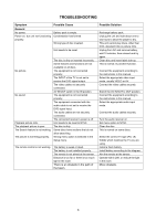
discs, other than DVD, standard CDs or picture CDs. Unplug from AC and remove battery, wait 10 minutes, then reinsert and try again. Clean disc and insert label side-up. This is normal; try another function. Connect the equipment according to the instructions in this manual. Select the appropriate - Memorex MVDP1085-BLW | Service Manual - Page 7
TROUBLESHOOTING Symptom DVD The unit does not start playback. Some functions do not operate as stated. Selected language is not being shown in the subtitles, or spoken. Subtitles are not working properly. Angle cannot be changed. Possible Cause DVD not inserted, or inserted upside-down. A non- - Memorex MVDP1085-BLW | Service Manual - Page 8
MPEG board (Top view) PRINTED CIRCUIT BOARDS Panel connector board (Top view) 8 - Memorex MVDP1085-BLW | Service Manual - Page 9
MPEG board (Bottom view) Panel connector board (Bottom view) 9 - Memorex MVDP1085-BLW | Service Manual - Page 10
DC Jack board (Top view) Panel switch board MEP1721 PANEL SWITCH-PCB P/N: 010E-1721000-03 REV:1 2007-03-13 94V0 Fr4 1.0mm Key board (Top view) - Memorex MVDP1085-BLW | Service Manual - Page 11
Charge board (Top view) Charge board (Bottom view) P/N.: 010E-1731102-05 MEP1731 Charge Board 94V0 Fr4 1.0mm (RoHS) REV: 1 Battery board (Top view) Battery board (Bottom view) B+ MEP1721 BATT. BOARD P/N: 010E-1721000-05 94V0 Fr4 1.0mm REV: 2.0 B- Led Back Light board (Top view) Led Back - Memorex MVDP1085-BLW | Service Manual - Page 12
-22 J9 12 P/N.: 1641-002040-10000 2 Pin #28 UL2651 L=40/3.5mm DC-JACK P/N.: 1641-115185-40000 15 Pin #30 UL1571 L=185mm Battery Rechargeable BATT1 BATTERY BOARD P/N: 010E-1721000-05 P/N: 1641-113275-40000 13Pin #30 UL1571 L=275 mm DVD Door Switch J10 SW2 J9 P/N: 1641-005020-20000 5Pin #22 - Memorex MVDP1085-BLW | Service Manual - Page 13
EXPLODED VIEW 14 15 13 2 12 14 11 16 17 18 19 8"TFT 8 17 21 18 20 22 47 23 43 3 33 24 3 17 25 10 9 1 7 75 3 6 4 5 26 28 11 29 64 63 29 62 61 60 59 58 31 30 20 34 20 11 32 11 35 37 51 36 20 38 50 54 57 20 56 32 55 46 53 52 27 65 66 69 67 68 72 73 74 46 - Memorex MVDP1085-BLW | Service Manual - Page 14
's Part No. 1 Top Cabinet MEP1761-05 Moulded Pink "Memorex" RoHS 1 3011-002601-00004 2 Cushion Eva 8 Pink RoHS 1 082E-0051721-00 27 Screw 2.6 x 6 BH/ST ZN RoHS 28 PCB MEP1721 DC 082E-1001731-14 38 MEP1731 Led Lens-Left RoHS 39 DVD Mechanism MG-9866H3H & HOP-1200X Pickup Head RoHS 40 - Memorex MVDP1085-BLW | Service Manual - Page 15
MAT'L= 0.8mm SUS304 RoHS MEP1721 TFT Rotating Stopper "R" Pink RoHS MEP1721 TFT Rotating Stopper "L" Pink RoHS MEP1761-05 Open Button Glossy Pink RoHS MEP1761-05 DVD Door Glossy Pink RoHS Screw 1.7 X 4 KH/ST ZN/Black (LF) Top Cabinet Battery MEP1761 Moulded White W/Spray ABS RoHS TFT Sponge Sheet - Memorex MVDP1085-BLW | Service Manual - Page 16
Main board ass'y ELECTRICAL PARTS LIST Ref. No. BC1 C1 C2 C3,4 C5 C6 C7 C8 C9 C10 C11 C12 C13 C14 C15 C16 C17 C18 C19,20 C21 C22,23 C24 C25 C26 C27 C28 C29 C30,31 C32 C33,34 C35 C36 C37 C38-41 C42 C43 C45 C47 C48 C50 C51 C53 C54,55 C56 C57 C58,59 C60 C61 C62,63 C65,66 C69,70 C72 C73-75 C78,79 - Memorex MVDP1085-BLW | Service Manual - Page 17
Ref. No. C80 C86 C87 C88 C89 C90 C91 C92 C93,94 C95 C96 C97 C98 C99 C100 C101 C102 C103 C104 C105 C106 C107 C108 C109 C110 C111,112 C113 C114 C115 C116 C117,118 C119 C120 C121 C122 C123,124 C125 C127 C138 C148 CB1 CB2 CB3,4 CB5 CB6 CB7 CB8-29 CB30 CB31-42 CB43 CB44-59 CB63,64 CB65-67 CB71 CB72 - Memorex MVDP1085-BLW | Service Manual - Page 18
-80 RoHS Diode BAT54S SMD (SOT-23) RoHS Diode LL4148 SMD SOD80 RoHS Diode LL4148 SMD SOD80 RoHS Leaf Switch KFC-P01-09-RS RoHS DVD Mechanism MG-9866H3H & HOP-1200X Pickup Head RoHS Electrolytic Capacitor 220 µF 16V 6.3 x 7 mm (LF) Electrolytic Capacitor 220 µF 16V 6.3 x 7 mm (LF) Fuse Time-Lag 32S - Memorex MVDP1085-BLW | Service Manual - Page 19
Ref. No. L1 L2 L3 L4 L5 L6 L7,8 L9 L10-14 L15,16 L17-23 L24,25 L26 L27 L28 L29 L30,31 L32 L34 L36-42 L43 L44 L45 L47 L48-53 L54 L55 L57-60 L62,63 Led1 Led2 Main Board Q2,3 Q6 Q7,8 Q9 Q10,11 Q12 Q13,14 R1 R2,3 R4 R5 R6 R7 R8 R9 R10 R11 R12-14 R15 R16 R17 R18 R19 ELECTRICAL PARTS LIST - CONTINUED - Memorex MVDP1085-BLW | Service Manual - Page 20
Ref. No. R20 R21 R22 R23 R24 R25 R26 R27 R28 R29,30 R31 R34 R35 R38 R39 R40 R43,44 R45-48 R49 R50-53 R54 R55 R56 R57 R58,59 R60 R61,62 R63 R64,65 R67 R68-70 R71 R72 R74,75 R76,77 R78 R80 R81 R82 R83 R84 R85 R86 R87 R88 R89 R90 R91 R92 R93 R94 R95 R96 R97 R98 ELECTRICAL PARTS LIST - CONTINUED - Memorex MVDP1085-BLW | Service Manual - Page 21
Ref. No. R99 R100 R101 R102 R103 R104 R105 R106 R107-111 R112-116 R117 R118 R119 R120 R122 R123 R124 R125 R126 R127 R128 R129 R131 R132 R133 R134 R135 R136 R138 R139 R140 R141 R142 R145 R147 R148 R149 R151 R152 R153 R154 R155 R156 R157 R158,159 R160 R161,162 R163,164 R165 R166 R167,168 R169 R170 - Memorex MVDP1085-BLW | Service Manual - Page 22
Header 2 Pin P=2mm B2BPH JST RoHS Header 2 Pin P=1.25mm H. Type Straight SMD RoHS TFT-LCD Module PW080XU4 8" W/Led Backlight RoHS IC DC/DC Converter MP9141ES SOIC8 RoHS IC DC/DC Converter MP2259DJ SOIC8 RoHS IC MPEG MT1389DE/P-L WITH DivX LQFP256 RoHS IC Motor Driver D5954 HSOP-28 RoHS IC Sdram 64MB - Memorex MVDP1085-BLW | Service Manual - Page 23
Charge board ELECTRICAL PARTS LIST - CONTINUED Ref. No. C1 C2 C3 C4,5 C6 C7,8 C9 C10 C11 C12,13 CN1 CN2 D1 D2 D3,4 F1 IC1 IC1 IC2 L1 L2 PCB Q1 Q2 Q3 Q4 Q6 R2 R3 R4 R5 R6 R7 R8 R9 R10 R13 R15 R22 R26 Description Electrolytic Capacitor 47 µF 16V ±20% 6.3 x 5 mm (LF) Ceramic Chip Capacitor 0.1 µF ± - Memorex MVDP1085-BLW | Service Manual - Page 24
ELECTRICAL PARTS LIST - CONTINUED TFT Connector board Ref. No. C1 C2 C3-5 CB2-10 CE3,4 CE5 CE7 CE10,11 CE14,15 CE27 Connector PCB Connector FPC/FFC J1 J2 J5 L1 L2,3 L4 L5-8 L10 L46,47 Q1-3 Q4 R2,3 R5 R7 R8 R9 R11 R12 R13 R14 R15 R16 R17 R18 R19 R20 R21 R22 R23 R24 R25 R26 R27 R28 R29 R30 R31 R32 - Memorex MVDP1085-BLW | Service Manual - Page 25
Wire #22 UL1007 4/50/4 mm Black/Red RoHS DC Jack DC-030 1.65 mm RoHS PCB MEP1721 DC Jack Board 94V0 FR4 1.0 mm RoHS Mfr's Part No. 076E-0020050-00 0271-017000-00009 010E-1721000-04 Battery pack ass'y Ref. No. Battery Battery Switch Cabinet Cabinet Connector PCB Polybag Rubber Screw Screw Sponge - Memorex MVDP1085-BLW | Service Manual - Page 26
222 APLLVDD 221 AVDD18_VPLL 220 VPLL_TST 219 AGND18_VPLL 218 VFE_TSTP/AUDIO_IN1 217 VFE_TSTN/AUDIO_IN2 216 AGND_VFE 215 CVBS_INP 214 AVDD33_VFE 213 CVBS_INN/BATTERY 212 AVDD33_ADC 211 AGND_ADC 210 DVDD33_ADC 209 DGND_ADC 208 SPDIF/GPIO23 207 GPIO12(MCDATA) 206 GPIO11(ASDATA4) 205 DVDD18 204 GPIO10 - Memorex MVDP1085-BLW | Service Manual - Page 27
MP2259 IN 5 EN 4 PB 3 GND 2 Regulator Reference Oscillator 1.4 MHz 1pF 27pF 400Kohm +-EA Error Amplifier D x20 Regulator Current sense Amplifier RSEN 25Mohm 1 BST + - Current Limit Comparator SQ R R Driver M1 6 SW + - PWM Comparator K4S641632 VDD 1 DQ0 2 VDDQ 3 DQ1 4 DQ2 5 VSSQ 6 DQ3 7 - Memorex MVDP1085-BLW | Service Manual - Page 28
TU24C02 A0 1 A1 2 A2 3 GND 4 2048 bit EEPROM array 7bit Address decorder 7bit Slave/word Address register 8bit Data register Start Stop Control Circuit ACK High-voltage Power supply generator Voltage detector 8 VCC 7 Start 6 SCL 5 SDA RT9284 VDD 6 OVP 5 EN 4 Current Bias ibias - Memorex MVDP1085-BLW | Service Manual - Page 29
RT9166 VIN D4556 OUT 1 1 -IN 1 2 +IN 1 3 Vee 4 Current Limiting Sensor Thermal Shutdown Error Amp -+ 1.2V Reference VOUT GND 8 Vcc 7 OUT 2 6 - IN 2 5 + IN 2 RT9166 3 VIN RT9166 1 GND 2 VOUT 8MS29AL008D Vcc RY/BY# Vss RESET# WE# BYTE# State Control Command Register CE# OE# Sector - Memorex MVDP1085-BLW | Service Manual - Page 30
ATtiny13 VCC GND Instruction Register Instruction Decoder Control Lines Stack Pointer 8-Bit Databus Watchdog Oscillator Sram Program Counter Program Flash General Purpose Registers X Y Z ALU Watchdog Timer MCU Control Register MCU Status - Memorex MVDP1085-BLW | Service Manual - Page 31
MPEG board SCHEMATIC DIAGRAMS Notes : 1. All resistance values are indicated in "ohms" (K=1000 ohms, M=1000 Kohms). 2. All capacitance values are indicated in "µF" (p=10-6 µF) 32 33 - Memorex MVDP1085-BLW | Service Manual - Page 32
Power board SCHEMATIC DIAGRAMS - CONTINUED Notes : 1. All resistance values are indicated in "ohms" (K=1000 ohms, M=1000 Kohms). 2. All capacitance values are indicated in "µF" (p=10-6 µF) 34 35 - Memorex MVDP1085-BLW | Service Manual - Page 33
Sdram & Flash & EEprom board SCHEMATIC DIAGRAMS - CONTINUED Notes : 1. All resistance values are indicated in "ohms" (K=1000 ohms, M=1000 Kohms). 2. All capacitance values are indicated in "µF" (p=10-6 µF) 36 37 - Memorex MVDP1085-BLW | Service Manual - Page 34
Video & TFT out board SCHEMATIC DIAGRAMS - CONTINUED Notes : 1. All resistance values are indicated in "ohms" (K=1000 ohms, M=1000 Kohms). 2. All capacitance values are indicated in "µF" (p=10-6 µF) 38 39 - Memorex MVDP1085-BLW | Service Manual - Page 35
Audio output board SCHEMATIC DIAGRAMS - CONTINUED Notes : 1. All resistance values are indicated in "ohms" (K=1000 ohms, M=1000 Kohms). 2. All capacitance values are indicated in "µF" (p=10-6 µF) 40 41 - Memorex MVDP1085-BLW | Service Manual - Page 36
SCHEMATIC DIAGRAMS - CONTINUED SD & USB I/F board Notes : 1. All resistance values are indicated in "ohms" (K=1000 ohms, M=1000 Kohms). 4. All capacitance values are indicated in "µF" (p=10-6 µF) 42 - Memorex MVDP1085-BLW | Service Manual - Page 37
SCHEMATIC DIAGRAMS - CONTINUED Panel connector board Notes : 1. All resistance values are indicated in "ohms" (K=1000 ohms, M=1000 Kohms). 5. All capacitance values are indicated in "µF" (p=10-6 µF) 43 - Memorex MVDP1085-BLW | Service Manual - Page 38
SCHEMATIC DIAGRAMS - CONTINUED Led back light board Notes : 1. All resistance values are indicated in "ohms" (K=1000 ohms, M=1000 Kohms). All capacitance values are indicated in "µF" (p=10-6 µF) 44 - Memorex MVDP1085-BLW | Service Manual - Page 39
Key board SCHEMATIC DIAGRAMS - CONTINUED Notes : 1. All resistance values are indicated in "ohms" (K=1000 ohms, M=1000 Kohms). 2. All capacitance values are indicated in "µF" (p=10-6 µF) 45 - Memorex MVDP1085-BLW | Service Manual - Page 40
Charge board SCHEMATIC DIAGRAMS - CONTINUED Notes : 1. All resistance values are indicated in "ohms" (K=1000 ohms, M=1000 Kohms). 2. All capacitance values are indicated in "µF" (p=10-6 µF) 46
-
 1
1 -
 2
2 -
 3
3 -
 4
4 -
 5
5 -
 6
6 -
 7
7 -
8
-
9
-
10
-
11
-
12
-
13
-
14
-
15
-
16
-
17
-
18
-
19
-
20
-
21
-
22
-
23
-
24
-
25
-
26
-
27
-
28
-
29
-
30
-
31
-
32
-
33
-
34
-
35
-
36
-
37
-
38
-
39
-
40
 |
 |

MVDP1085-FLRP
8
°
TFT DISPLAY PORTABLE DVD PLAYER
CONTENTS
Page
S
PECIFICATIONS
................................................................................................................................................
2
B
LOCK
D
IAGRAM
................................................................................................................................................
3
D
ISASSEMBLY
I
NSTRUCTIONS
.............................................................................................................................
4
S
AFETY
C
HECKS
................................................................................................................................................
5
T
ROUBLESHOOTING
...........................................................................................................................................
6
P
RINTED
C
IRCUIT
B
OARDS
.................................................................................................................................
8
W
IRING
D
IAGRAM
............................................................................................................................................
12
E
XPLODED
V
IEW
..............................................................................................................................................
14
M
ECHANICAL
P
ARTS
L
IST
.................................................................................................................................
15
E
LECTRICAL
P
ARTS
L
IST
..................................................................................................................................
17
IC L
EAD
I
DENTIFICATION AND
I
NTERNAL
D
IAGRAM
.............................................................................................
27
S
CHEMATIC
D
IAGRAM
......................................................................................................................................
32