NEC 1090025 Hardware Manual
NEC 1090025 - PHONE DSX 22Button Display WH Manual
 |
UPC - 961613053657
View all NEC 1090025 manuals
Add to My Manuals
Save this manual to your list of manuals |
NEC 1090025 manual content summary:
- NEC 1090025 | Hardware Manual - Page 1
Components Installation Optional Specifications Equipment and Parts Empowered by Innovation DSX-40 Hardware Manual P/N 1093097 Rev 1, October 2006 Printed in U.S.A. 01.01.09 For additional resources, visit our Technical Support site on the web at http://www.necdsx.com. - NEC 1090025 | Hardware Manual - Page 2
for the use of its customers and service personnel, and should be read in its entirety before attempting to install or program the system. Any comments or suggestions for improving this manual would be appreciated. Forward your remarks to: NEC Unified Solutions, Inc. 4 Forest Parkway Shelton, CT - NEC 1090025 | Hardware Manual - Page 3
Table of Contents Components 1 DSX Telephones 1 22-Button Display Telephone with Speakerphone 1 34-Button Backlit Display Telephone with Speakerphone 1 34-Button Backlit Display Telephone with Full-Duplex Speakerphone 2 34-Button Backlit Super Display Telephone with Half-Duplex Speakerphone - NEC 1090025 | Hardware Manual - Page 4
the 2PGDAD Module and Connecting to the System 53 External Paging 54 Installing External Paging 54 Music Source 55 Installing a Music Source 55 Power Failure Telephone 56 ii ◆ Table of Contents DSX-40 Hardware Manual - NEC 1090025 | Hardware Manual - Page 5
the Keyset 62 Connecting a PC to the System 63 Connections for PC Programming (System Administrator) and SMDR 63 Specifications and Parts 65 Specifications 65 DSX Telephone System Specifications 65 DSX IntraMail Specifications 70 Parts List 71 DSX-40 Hardware Manual Table of Contents ◆ iii - NEC 1090025 | Hardware Manual - Page 6
Table of Contents iv ◆ Table of Contents DSX-40 Hardware Manual - NEC 1090025 | Hardware Manual - Page 7
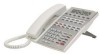
DSX Telephones Components Components DSX Telephones DSX Telephones 22-Button Display Telephone with Speakerphone At a Glance P/Ns 1090020 (Black) and 1090025 (White) Display: 3 line x 24 character Speakerphone: Built-in, half-duplex Soft Keys: 4 Wall Mount: Built-in Feature Keys: 12 - NEC 1090025 | Hardware Manual - Page 8
DSX Telephones 34-Button Backlit Display Telephone with Full-Duplex Speakerphone At a Glance P/Ns 1090022 (Black) and 1090027 (White) Display: 3 line x 24 character /160 supports DS1000/2000 telephones if the system has a DSTU Card (P/N 80021A) installed. 2 ◆ Components DSX-40 Hardware Manual - NEC 1090025 | Hardware Manual - Page 9
. To simplify working in groups, The DTH-1-1 provides 3 selectable ring tones. At a Glance DTR-1-1 Single Line Telephone P/Ns 780020 (Black) and Monitor) and 8 Speed Dial bin keys. For convenient on-hook dialing and call monitor, the DTR-1HM-1 also offers Handsfree Monitor. DSX-40 Hardware Manual - NEC 1090025 | Hardware Manual - Page 10
LEDs), the DSX Cordless Lite II Telephone achieves a whole new level of convenience and mobility. An easy-to-read 16-character by 2-line LCD display (with four Handset Charger Wall Mount Bracket (P/N 730633) Handset Battery (P/N 730631) Belt Clip (P/N 730634) 4 ◆ Components DSX-40 Hardware Manual - NEC 1090025 | Hardware Manual - Page 11
DSX Keysets and DTR/DTH SLTs The following corded headsets are compatible with DSX keysets and the DTR/DTH single line telephones. Check with your supplier for their latest offerings. NEC / Plantronics Headsets NEC P251 P251N P261 P261N P351 P351N P361 P361N DSX-40 Hardware Manual Components ◆ 5 - NEC 1090025 | Hardware Manual - Page 12
Headsets NEC P/N - NEC / Plantronics Non-Amplified Headsets 1 (http://www.plantronics.com) Description Polaris StarSet Polaris Mirage Polaris Supra Monaural Polaris H141N H151 H151N H161 H161N H171 H171N H181 H181N H251 H251N H261 H261N H351 H351N H361 H361N 6 ◆ Components DSX-40 Hardware Manual - NEC 1090025 | Hardware Manual - Page 13
Components NEC P/N 750655 750657 750656 750 650 750651 750653 750652 750654 Headsets Accessories and Replacement Parts for Polaris Headsets Description Polaris Extension Cable 17593-01 or 17593-06 17593-7 or 17593-80 29960-01 or 29960-13 29960-70 or 29960-80 DSX-40 Hardware Manual Components ◆ 7 - NEC 1090025 | Hardware Manual - Page 14
-the-Head Over-the-Head Over-the-Head Over-the-Head On-the-Ear On-the-Ear Under-the-Chin or Behind-the-Neck 8 ◆ Components DSX-40 Hardware Manual - NEC 1090025 | Hardware Manual - Page 15
M175) Headsets P/N 750642 (MX150) At a Glance P/N 730602 (EXP9530) The following headsets are available for the DSX Cordless Lite II Telephone: • M175 Headband Style (P/N 750637) • MX150 Earloop Style (P/N 750642) • EXP 9350 Convertible Headset (P/N 730602) DSX-40 Hardware Manual Components ◆ 9 - NEC 1090025 | Hardware Manual - Page 16
-compatible application for printing customized key data on specially designed DESI telephone labels. Use DESI Plus Labeling Software to create quick, professional Software is provided on the DSX System Document CD included with each DSX telephone system. 10 ◆ Components DSX-40 Hardware Manual - NEC 1090025 | Hardware Manual - Page 17
DSX Telephones DESI Telephone Label System Labels for NEC Single Line Telephones At a Glance Components The following DESI labels are available for DSX telephone "replacement" applications. • 22-Button Display ) • For DTH-1-1 - Metallic silver (P/N 780450) DSX-40 Hardware Manual Components ◆ 11 - NEC 1090025 | Hardware Manual - Page 18
-40 Common Equipment DSX-40 Common Equipment DSX-40 4x8x2 Key Telephone System with 2 Door Box Ports and Caller-ID At a Glance P/N 1090001 Digital extension ports: Built-in: 8 Fully expanded: 24 Analog extension ports: Built-in: 2 Fully expanded: 18 Built-in door box ports: 2 Built-in door box - NEC 1090025 | Hardware Manual - Page 19
(8 in each analog card installed plus 2 built-in) Installs in either the top or middle DSX-40 expansion slot Can be mixed with 8-Port Digital Station Cards in any combination in the top Analog Station Cards use the same expansion slots (upper and middle). DSX-40 Hardware Manual Components ◆ 13 - NEC 1090025 | Hardware Manual - Page 20
-40 PCBs DSX-40 4 Port (4COIU) Line PCB with Caller ID At a Glance P/N 1091001 Line ports: 4 Max. line cards installed: 1 (4 additional CO line ports) Max remember: • You can install the 4-Port CO Line Card with Caller ID only in the bottom expansion slot. 14 ◆ Components DSX-40 Hardware Manual - NEC 1090025 | Hardware Manual - Page 21
Group Mailboxes: 8 Total Mailboxes: DSX-40: 66 Storage Hours: 8 Subscirber Mailboxes: DSX-40: 34 UCD Group Mailboxes Soft Keys guide the display telephone user through Instruction Menu message (greeting) to the caller and provides them with dialing options. DSX-40 Hardware Manual Components ◆ 15 - NEC 1090025 | Hardware Manual - Page 22
922450 DSX-40: • 2 built-in door box ports • Additional door box ports requires 2PGDAD Modules connected to Digital Station ports • At a Glance The Analog Door Box is a self-contained Intercom unit typically used to monitor an entrance door. A visitor at the door can press the Door Box call button - NEC 1090025 | Hardware Manual - Page 23
DSX System Administrator is a WindowsTM-based application you can use for programming the telephone system and maintaining site databases, instead of using the conventional telephone telephone system's USB or Ethernet port, you can make immediate changes to the telephone to the telephone system, and - NEC 1090025 | Hardware Manual - Page 24
Miscellaneous Cards and Optional Equipment 18 ◆ Components DSX-40 Hardware Manual - NEC 1090025 | Hardware Manual - Page 25
DSX-40 (page 20) and shows you about how much space your system requires. Single Line Telephone REN Limitations Please note the following when installing single line telephones ringer. Many phones with electronic ringers have significantly lower RENs. DSX-40 Hardware Manual Installation ◆ 19 - NEC 1090025 | Hardware Manual - Page 26
practices and local codes. See Figure 1: Installation Layout, DSX-40 below. The to the right of the cabinet Important Local codes may prohibit you from installing extensions, trunks Station Station Block Block Surge Protector To electrical service ground Dedicated AC Outlet Note: The system - NEC 1090025 | Hardware Manual - Page 27
to access the extension, line and auxiliary connections. To remove the cover: 1. Slide the cover button to OPEN. 2. Press down and slide the cover away from the Main Equipment Cabinet. 1093097 - 2 Push button to "OPEN" position Figure 2: Removing the Cover DSX-40 Hardware Manual Installation ◆ 21 - NEC 1090025 | Hardware Manual - Page 28
leave the fasten- ers "backed out" about 3/16" from the MDF backboard. 2. Hang the cabinet as shown. 1093097 - 3 11 - 7/32" 7 - 3/32" Figure 3: Hanging the Cabinet 22 ◆ Installation DSX-40 Hardware Manual - NEC 1090025 | Hardware Manual - Page 29
Attaching the Ground Wire Important You must connect your system to Electrical Service Ground. To attach the ground wire: 1. Loosen the lug on from the ground lug to Electrical Service Ground. 3. Firmly retighten the lug loosened in step 1 above. To Electrical Service Ground Figure 4: Attaching the - NEC 1090025 | Hardware Manual - Page 30
top panel to the base. 2. Lift up the top panel as shown below. 3. Remove the top panel. 2 3 1 1093097 - 5 24 ◆ Installation Figure 5: Removing the Top Panel DSX-40 Hardware Manual - NEC 1090025 | Hardware Manual - Page 31
Replacement Fuses Installing Expansion Cards The DSX-40 accepts up to 3 Expansion Port Digital Card 8-Port Digital Card 8-Port Analog Card DSX-40 Station Card Capacities Middle Position (17-14) the 4-port line card. This allows you do expand the DSX-40 from 4 lines to 8 lines, all with built-in - NEC 1090025 | Hardware Manual - Page 32
the top panel. OR Go to Installing Expansion Cards (page 25) and install Expansion Cards as required. Battery Figure 7: Installing the Battery 1093097 - 6 26 ◆ Installation DSX-40 Hardware Manual - NEC 1090025 | Hardware Manual - Page 33
or equivalent. (This battery is avail- able from NEC as P/N EX0254-0040.) 4. Verify that the Real instructions. Power Supply AC Input Fuses The power supply AC input fuses protect the system power supply from problems with the site's AC line. These problems DSX-40 Hardware Manual Installation ◆ 27 - NEC 1090025 | Hardware Manual - Page 34
in the middle position. STA 21-24 Second 4 station ports in the middle position STA 25-26 Door 1-2 Built-in analog station ports. See Installing a DSX Analog Door Box on a BuiltIn Door Box Port (page 49). CO 1-4 CO 5-8 Four built-in lines. Four additional lines provided by the line expansion - NEC 1090025 | Hardware Manual - Page 35
Connecting Extensions and Lines 3 Line Block Installation 1093097 - 8 1 2 Cable 1 Cable 2 Cable 3 Station Block Station Block Figure 8: Extension and Line Cabling DSX-40 Hardware Manual Installation ◆ 29 - NEC 1090025 | Hardware Manual - Page 36
66M1-50 block, punch down the Installation Cable in standard color-code order. 1093097 - 9 To make your own cables, see Making 4 19 RED-SLT 309 T 3 3 20 SLT-RED 309 R 21 BLK-BLU 310 T 6 2 22 BLU-BLK 310 R 7 23 BLK-ORN 311 T 1 24 ORN-BLK 311 R 8 25 BLK-GRN 312 DSX-40 Hardware Manual - NEC 1090025 | Hardware Manual - Page 37
punch down the Installation Cable in standard color-code order. To make your own cables, see Making 19 RED-SLT 20 SLT-RED 21 BLK-BLU 22 BLU-BLK 23 BLK-ORN 24 ORN-BLK NC 2 7 1 8 5 4 3 6 2 7 1 8 5 4 3 6 2 7 1 8 5 4 3 6 2 7 1 8 Figure 10: Punch Down for Lines DSX-40 Hardware Manual Installation ◆ 31 - NEC 1090025 | Hardware Manual - Page 38
power cord strain relief and install the cord as shown below. 1093097 - 14 Figure 12: Installing the AC Power Cord and Strain Relief 32 ◆ Installation DSX-40 Hardware Manual - NEC 1090025 | Hardware Manual - Page 39
(RJ61X) Jack Pinouts Connecting Extensions A fully expanded DSX-40 can connect up to 26 extensions. The 30) as a guide, plug the installation cable extension within 6 feet of the telephone's location. 3. For each changes easier, be sure to leave a service loop in your station cable. 4. Terminate - NEC 1090025 | Hardware Manual - Page 40
12 25-PAIR CABLE BLOCK COLOR RJ61X TERM CODE FUNCTION 1 WHT-BLU 300 T 2 BLU BLK WHT-BLU GRN 25-PAIR CABLE BLOCK COLOR RJ61X TERM CODE FUNCTION 1 WHT-BLU 324 T 2 BLU-WHT 324 R 625 Modular Jack BLK WHT-BLU GRN DSX Keyset 300 DTH-1-1 324 Figure 14: Connecting Extensions 34 ◆ Installation - NEC 1090025 | Hardware Manual - Page 41
for more. To connect lines: 1. Using Figure 10: Punch Down for Lines (page 31) as a guide, plug the installation cable plugs into the appropriate jacks on the Main Equipment Cabinet. 2. For each line : Installing Analog Lines 25-Pair Cable to Central Office DSX-40 Hardware Manual Installation ◆ 35 - NEC 1090025 | Hardware Manual - Page 42
Headset When installing an optional headset, plug the headset cord in the headset jack on the bottom of the telephone. The headset cord routes through the upper channel on the right side of the telephone base. 36 ◆ Installation Figure 17: Installing the Optional Headset DSX-40 Hardware Manual - NEC 1090025 | Hardware Manual - Page 43
Card, just like a keyset. You can install four maximum per system. The DSS Console line cord does not use a channel and drapes down from the telephone line cord jack or connects to the telephone legs. Line Cord can be installed either way 1093096 - 23 Figure 18: Installing the DSS Console Line Cord - NEC 1090025 | Hardware Manual - Page 44
Up the Telephone and DSS Console Keyset and DSS Console Two Position Angle Adjustment To set the low viewing angle position: 1. Fold the legs all the way back. 1093096 - 34 1 Figure 19: Setting the Low Viewing Angle To set the high viewing angle position: 1. Flip up the two leg supports. 2. Fold the - NEC 1090025 | Hardware Manual - Page 45
the telephone faceplate to write on the label or install a DESI custom label. To remove the faceplate: 1. Put your finger in the recessed area under the faceplate and lift off the faceplate. - 36 1093096 Installation Figure 21: Removing the Telephone Faceplate DSX-40 Hardware Manual Installation - NEC 1090025 | Hardware Manual - Page 46
Setting Up the Telephone and DSS Console To reinstall the faceplate: 1. Snap back into place as shown. 40 ◆ Installation Figure 22: Reinstalling the Telephone Faceplate DSX-40 Hardware Manual - NEC 1090025 | Hardware Manual - Page 47
. • After about 45 seconds, the LED will wink off blue continuously and the system will be operational. Installation 1093097 - 15 Power Switch AC Power Cord DSX-40 Hardware Manual Installation ◆ 41 - NEC 1090025 | Hardware Manual - Page 48
Powering Up the System Figure 23: Power Switch and AC Power Cord Power LED Figure 24: Power LED 1093097 - 16 42 ◆ Installation DSX-40 Hardware Manual - NEC 1090025 | Hardware Manual - Page 49
and running, you should reinstall the cover. To reinstall the cover: 1. Slide the cover onto the Main Equipment Cabinet as shown. 2. Slide the cover button to LOCK. 1093097 - 17 Installation Push button to "LOCK" position Figure 25: Reinstalling the Cover DSX-40 Hardware Manual Installation ◆ 43 - NEC 1090025 | Hardware Manual - Page 50
blue continuously and the system will be operational. • Resetting the system does not erase system programming. 1 1093097 - 18 Figure 26: Resetting the System 44 ◆ Installation DSX-40 Hardware Manual - NEC 1090025 | Hardware Manual - Page 51
seconds, the LED will wink off blue continuously and the system will restart with the default settings. 2, 3 Installation 1093097 - 19 Figure 27: Initializing the System DSX-40 Hardware Manual Installation ◆ 45 - NEC 1090025 | Hardware Manual - Page 52
the software upgrade CompactFlash card. - Insert the IntraMail CompactFlash card. - Reset the system. 1 2 1093097 - 20 Figure 28: Loading System Software from a CompactFlash Card 46 ◆ Installation DSX-40 Hardware Manual - NEC 1090025 | Hardware Manual - Page 53
default system (with no voice mail installed) provides the Built-In Automated Attendant. See Automated Attendant, Built-In in the IntraMail section of the Software Manual for more. ■ If you have another (external) voice mail installed, you must disconnect and unprogram it before installing IntraMail - NEC 1090025 | Hardware Manual - Page 54
- If updating from the Built-In Automated Attendant, just rerecord your Instruction Menu Messages. Your Answer Schedule and Dial Action Table programing remain intact. of the System Guide for more. 1 2 1093097 - 21 Figure 29: Installing IntraMail 48 ◆ Optional Equipment DSX-40 Hardware Manual - NEC 1090025 | Hardware Manual - Page 55
to monitor an entrance door. A visitor at the door can press the DSX Analog Door Box call button (like ) as a guide, on Station Block 2 punch down the Installation Cable in standard color code-order. 2. Plug DSX Software Manual for programming details. DSX-40 Hardware Manual Optional Equipment ◆ 49 - NEC 1090025 | Hardware Manual - Page 56
Installing a DSX Analog Door Box on a Built-In Door Box Port 1093097 - 27 25-PAIR CABLE BLOCK COLOR RJ61X TERM CODE FUNCTION 1 WHT-BLU 324 T 2 BLU-WHT 324 R 3 You can also connect a DSX Analog Door Box to a 2PGDAD Module. See Installing a DSX Analog Door Box and 2PGDAD Module (page 51) - NEC 1090025 | Hardware Manual - Page 57
DSX keyset. - When choosing a location, keep in mind that the front side of the module contains the status LEDs (important for troubleshooting) Station Port 1093097 - 22 Not Used Remove Prior to Cabling Figure 31: Removing the 2PGDAD Module Cover DSX-40 Hardware Manual Optional Equipment ◆ 51 - NEC 1090025 | Hardware Manual - Page 58
the relay location to the 2PGDAD Module. 2. At the relay, connect the station cable following the instructions provided with the relay. 3. At the 2PGDAD Module, strip the wires about 1/4" and connect to the 32: Connecting PGDAD Door Boxes and Relays 52 ◆ Optional Equipment DSX-40 Hardware Manual - NEC 1090025 | Hardware Manual - Page 59
(96-127 by default). - In 2113-02: Ring Group, assign the extensions associated with the 2PGDAD Module and all telephones that should receive door chimes to the same Ring Group. - Refer to the Door Box feature in the DSX Software Manual for additional programming. 4. Using a standard line cord, plug - NEC 1090025 | Hardware Manual - Page 60
cable into the paging amplfier. 1093097 - 24 Audio Out Audio Cable To customer-provided paging amplifier Figure 34: Connecting External Paging 54 ◆ Optional Equipment DSX-40 Hardware Manual - NEC 1090025 | Hardware Manual - Page 61
the other end of the audio cable into the music source. Optional Equipment 1093097 - 25 Audio In 1 Audio In 2 Audio Cables DSX-40 Hardware Manual To customer-provided music sources (assigned in programming to Background Music and Music On Hold) Figure 35: Connecting a Music Source Optional - NEC 1090025 | Hardware Manual - Page 62
fails, the system can automatically cut through to a Power Failure Telephone connection. Analog stations 25 and 26 (extensions 324 and 325) To test the Power Failure Telephone: 1. Connect the power failure telephone. 2. Power down the system. 3. At the Power Failure Telephone, lift the handset. - - NEC 1090025 | Hardware Manual - Page 63
in place while the telephone is mounted on the wall. To reverse the wall-mount handset hanger: 1. Slide out the handset hanger. 2. Reverse and re-insert the handset hanger. Optional Equipment 1093096 - 29 Figure 36: Reversing the Handset Hanger DSX-40 Hardware Manual Optional Equipment ◆ 57 - NEC 1090025 | Hardware Manual - Page 64
the two leg supports down flush with the legs. 5. Plug a short line cord into the telephone base. • telephone on top of the wall plate and slide into place. 1 7 1093096 - 31 4 4 6 7 3 2 5 Figure 37: Mounting the Telephone to a Standard Wall Plate 58 ◆ Optional Equipment DSX-40 Hardware Manual - NEC 1090025 | Hardware Manual - Page 65
leg supports down flush with the legs. 5. Place the telephone on top of the wall plate and slide into place. 6. Plug the line cord into the telephone's mod jack. 1093096 - 30 5 4 1 4 5 3 2 Optional Equipment 6 Figure 38: Mounting the Telephone Directly on the Wall DSX-40 Hardware Manual - NEC 1090025 | Hardware Manual - Page 66
convenient location. 2. Fold the DSS Console legs into the wall mount position. 3. Fold the two leg supports down flush with the legs. 4. Plug a short line cord into the DSS Console base. • If Figure 39: Mounting the DSS Console to a Standard Wall Plate 60 ◆ Optional Equipment DSX-40 Hardware Manual - NEC 1090025 | Hardware Manual - Page 67
Console legs into the wall mount position. 3. Make sure the line cord is routed through the lower channel in the base. 4. Fold the two leg supports down flush with the legs. 5. Place the DSS Console on top of the wall plate and slide into place. 6. Plug the line cord into the - NEC 1090025 | Hardware Manual - Page 68
DSX display you see:TEST PUSH - If you don't see this display, repeat the procedure and hold the keys down a little longer. To test a key: 1. Press the key. - The code display Dial bins 1-10 Super Display Soft Keys1 CLEAR FLASH a Super Display Soft Key is pressed, 12 # characters display adjacent to - NEC 1090025 | Hardware Manual - Page 69
Adaptor Serial Port RJ11 Jack 6 pin, 6 conductor 123456 DB9 Female Front View 54321 9876 The DSX SMDR Adaptor is P/N 1091014. RJ11 DTR 1 TXD 2 GND 3 GND 4 RXD 5 DSR 6 Figure 41: Connecting a PC to the System DB9 4 DSR 3 RXD 5 GND NC 2 TXD 1 DTR DSX-40 Hardware Manual Optional Equipment ◆ 63 - NEC 1090025 | Hardware Manual - Page 70
Connecting a PC to the System 64 ◆ Optional Equipment DSX-40 Hardware Manual - NEC 1090025 | Hardware Manual - Page 71
Ports (Built-In) 2 DSX Analog Door Boxes (With 2PGDAD Modules) Power Failure Telephones: Internal Paging Zones: External Page Audio Output: Max. limited only by number of available digital station ports for 2PGDAD Modules. 2 8 (7 and All Call) 1 DSX-40 Hardware Manual Specifications and Parts - NEC 1090025 | Hardware Manual - Page 72
Expansion) 32 Conference circuits dynamically allocated, with 8 parties max per Conference. Conference circuits provided on system. Refer to the Standard Practices Manual for further information. Be sure that Telephones Temperature: Humidity: 0 to 40oC (32-104oF) 10 to 95% (non-condensing) DSX - NEC 1090025 | Hardware Manual - Page 73
: Grounding Requirements: DSX-40 Electrical Specifications 120 VAC + 10% @ 50-60 Hz 83 Watts @ 100% full load 1.1A 132 VA 0.132 KwH 450 Btu 12 AWG copper wire Telephone and Line Voltages Output Level: External Paging 600 Ohm 0 dBr @ 1.0 KHz DSX-40 Hardware Manual Specifications and Parts ◆ 67 - NEC 1090025 | Hardware Manual - Page 74
Specifications Equipment DSX-40 Cabinet Display Keyset: Super Display Keyset: 60-Button DSS Console DSX Analog Door Box Mechanical Specifications Width 13 3/16" Depth 2 dBr (+ 2 dBr) @ 1.0 Khz USB and Ethernet Specifications DSX-40 USB and ethernet connectors are located on the cabinet. USB: - NEC 1090025 | Hardware Manual - Page 75
Port ID Original 02LS2 1090001 1091001 NEC Infrontia Class B US:NIFKF00BDSX US:NIFMF00BDSX US:NIFPF00BDSX IC: 140k-DSX REN Network Jacks REN Run (ft) Notes Key Telephone 2-wire 26 AWG 2-wire 24 AWG 1300 2000 Single Line Telephone 2-wire 26 AWG 2-wire 24 AWG 2-wire 22 AWG 11,500 3150 - NEC 1090025 | Hardware Manual - Page 76
per message (default): Ports: Storage Hours: IntraMail 4 Port/8 Hour IntraMail 8 Port/16 Hour DSX-40 Routing Mailboxes 16 Announcement: . . . 8 Call Routing: . . . . . 8 Subscriber 34 Ring Group Mailboxes 8 UCD Group Mailboxes 8 Total 66 300 = 99, all others = 20 120 seconds 4 or 8 8 or 16 - NEC 1090025 | Hardware Manual - Page 77
22-Button Display Telephone with Speakerphone 34-Button Backlit Display Telephone with Speakerphone 34-Button Backlit Display Telephone with Full-Duplex Speakerphone 34-Button Backlit Super Display Telephone with Half-Duplex Speakerphone 60-Button DSX-40 Hardware Manual Specifications and Parts ◆ 71 - NEC 1090025 | Hardware Manual - Page 78
) DSX 22-Button Display Telephone (White) 1093086 DSX 22-Button Display Telephone (Black) 1093085 DSX 34-Button Display Telephone (White) 1093084 DSX 34-Button Display Telephone (Black) 1093083 DSX 34-Button Super Display Telephone (White) 1093082 DSX 34-Button Super Display Telephone - NEC 1090025 | Hardware Manual - Page 79
ID (Expansion) Description IntraMail 8 Port x 16 Hour IntraMail 4 Port x 8 Hour IntraMail Parts List Part Number Part Number 1090001 808920 1091014 Part Number 1091002 1091003 1091001 Part Number 1091013 1091011 Specifications and Parts DSX-40 Hardware Manual Specifications and Parts ◆ 73 - NEC 1090025 | Hardware Manual - Page 80
Cover (pkg 5) 34 Button Super Display Clear Plastic Cover (pkg 5) 60 Button DSS Clear Plastic Cover (pkg 5) RFI Bead Kit Replacement Battery for CPU Part Number 1091016 1091038 1091018 1091019 1091020 1091021 88901 EX0254-0040 (Sony CR2032) 74 ◆ Specifications and Parts DSX-40 Hardware Manual - NEC 1090025 | Hardware Manual - Page 81
NEC Unified Solutions, Inc. 4 Forest Parkway, Shelton, CT 06484 Tel: 800-365-1928 Fax: 203-926-5458 www.necunifiedsolutions.com Other Important Telephone Numbers Sales 203-926-5450 Customer Service 203-926-5444 Customer Service FAX 203-926-5454 Technical Service 203-925-8801 Discontinued Product - NEC 1090025 | Hardware Manual - Page 82
(1093097) October 26, 2006, Rev 1 NEC Unified Solutions, Inc. 4 Forest Parkway, Shelton, CT 06484 TEL: 203-926-5400 FAX: 203-929-0535 www.necunifiedsolutions.com Printed in U.S.A.
-
 1
1 -
 2
2 -
 3
3 -
 4
4 -
 5
5 -
 6
6 -
 7
7 -
8
-
9
-
10
-
11
-
12
-
13
-
14
-
15
-
16
-
17
-
18
-
19
-
20
-
21
-
22
-
23
-
24
-
25
-
26
-
27
-
28
-
29
-
30
-
31
-
32
-
33
-
34
-
35
-
36
-
37
-
38
-
39
-
40
-
41
-
42
-
43
-
44
-
45
-
46
-
47
-
48
-
49
-
50
-
51
-
52
-
53
-
54
-
55
-
56
-
57
-
58
-
59
-
60
-
61
-
62
-
63
-
64
-
65
-
66
-
67
-
68
-
69
-
70
-
71
-
72
-
73
-
74
-
75
-
76
-
77
-
78
-
79
-
80
-
81
-
82
 |
 |

Optional
Equipment
For additional resources, visit our Technical Support site on the web at
.
Components
Installation
Specifications
and Parts
DSX-40 Hardware Manual
P/N 1093097
Rev 1, October 2006
Printed in U.S.A
.
01.01.09
Empowered by Innovation