NEC 4001-20B User Manual
NEC 4001-20B - Voclan Advertisement Display Manual
 |
UPC - 897204001496
View all NEC 4001-20B manuals
Add to My Manuals
Save this manual to your list of manuals |
NEC 4001-20B manual content summary:
- NEC 4001-20B | User Manual - Page 1
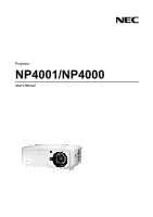
Projector NP4001/NP4000 User's Manual - NEC 4001-20B | User Manual - Page 2
to change without notice. (3) Great care has been taken in the preparation of this user's manual; however, should you notice any questionable points, errors or omissions, please contact us. (4) Notwithstanding article (3), NEC will not be responsible for any claims on loss of profit or other matters - NEC 4001-20B | User Manual - Page 3
this manual carefully before using your NEC NP4001/NP4000 projector and keep the manual handy HIGH-VOLTAGE COMPONENTS INSIDE. • REFER SERVICING TO QUALIFIED SERVICE PERSONNEL. This symbol warns the user . The information should be read carefully to avoid problems. WARNING: To prevent fire or shock, do - NEC 4001-20B | User Manual - Page 4
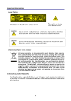
Important Information Laser Rating This label is on the side of the remote control. This mark is on the top of the remote control. CAUTION Use of controls or adjustments or performance of procedures other than those specified herein may result in hazardous radiation exposure. CAUTION Do not - NEC 4001-20B | User Manual - Page 5
to the unit EXCEPT those specified by NEC Display Solutions of America, Inc. in this manual. Failure to comply with this government supplied with this equipment please contact your supplier. Important Safeguards These safety instructions are to ensure the long life of your projector and to prevent - NEC 4001-20B | User Manual - Page 6
technicians in order to ensure proper operation and reduce the risk of bodily injury. ƒ In addition, the ceiling must be strong enough to support the projector and the installation must be in accordance with any local building codes. ƒ Please consult your dealer for more information. CAUTION: When - NEC 4001-20B | User Manual - Page 7
into your projector, disconnect it immediately and have the object removed by qualified service personnel. • Do not place any objects on top of the projector. or fire. ƒ Do not use any power cables other than the one supplied by NEC. ƒ Do not bend or tug the power cable excessively. ƒ Do not place - NEC 4001-20B | User Manual - Page 8
the projector does not operate normally when you follow the instructions described in this user's manual. ƒ If the projector has been dropped or the . • Do not send the projector in the soft case by parcel delivery service or cargo shipment. The projector inside the soft case could be damaged. - NEC 4001-20B | User Manual - Page 9
different types of batteries together. • Dispose of used batteries according to your local regulations. Lamp Replacement To replace either of the lamps, follow all instructions provided on page 107. Be sure to replace the lamp when the following is displayed on the screen: If you continue to use the - NEC 4001-20B | User Manual - Page 10
PROJECTOR ...37 Note on Startup Screen (Menu Language Select screen 38 o SELECTING A SOURCE ...39 p ADJUSTING THE PICTURE POSITION AND PICTURE SIZE 40 Adjusting Picture Position Manually 40 viii - NEC 4001-20B | User Manual - Page 11
Power Off...48 After Use...48 4. CONVENIENT FEATURES ...49 n TURNING OFF THE IMAGE AND SOUND 49 o FREEZING A PICTURE ...49 p ADJUSTING THE FOCUS/ZOOM MANUALLY 50 Adjusting by Using the OSD Control Panel 50 q CHANGING LAMP MODE ...51 Changing Lamp Mode by Using the Projector's OSD Control Panel - NEC 4001-20B | User Manual - Page 12
...112 Indicator Messages...112 Common Problems and Solutions 114 Tips for Troubleshooting...114 p IMAGE PROBLEMS ...115 Lamp Problems...116 Remote Control Problems...116 Audio Problems ...117 q HAVING THE PROJECTOR SERVICED 118 8. SPECIFICATIONS...119 n PROJECTOR SPECIFICATIONS...119 - NEC 4001-20B | User Manual - Page 13
(79TD5521) (with Two AA alkaline batteries) ƒ Quick setup guide (79TD5741) Important Information (79TD5751) ƒ For North America Only: Europe only: Guarantee Policy ƒ For Japan Only: User's manual Warranty card CD-ROM (This User's manual) (79TD5501) 6 Segment Color Wheel (79TD5371) Lens Hole - NEC 4001-20B | User Manual - Page 14
button on the remote control or projector cabinet. z A variety of input ports and a comprehensive array of system control interfaces This projector supports input signals including BNC, DVI-D, analog RGB, component, S-video, and composite. z 3W+3W Stereo speaker Built in 3W x 2 speakers are provided - NEC 4001-20B | User Manual - Page 15
p Part Names of the Projector Front-right view 1. Introduction ITEM 1. 2. 3. LABEL IR receiver Lamp cover Lens control panel DESCRIPTION Receiver for IR signal from remote control Remove cover to replace lamp or color wheel See Lens Controls SEE PAGE: 12 107 7 4. OSD control panel See OSD - NEC 4001-20B | User Manual - Page 16
1. Introduction Top View ITEM LABEL 1. Lens control panel 2. Right-hand speaker 3. Lamp cover 4. Exhaust vent 5. OSD control panel 6. Rear intake vent 7. Left intake vent DESCRIPTION See Lens Controls 3 SEE PAGE: 7 Right-hand speaker - Remove cover to replace lamp or color wheel - NEC 4001-20B | User Manual - Page 17
projector or when the projector is not in use, cover the lens with the lens cap. To extend the projector handle, refer to the following guide. 1. Stand the projector on its end with the control panels at the bottom. Note: Stand the projector on its end by lifting the cabinet. Do - NEC 4001-20B | User Manual - Page 18
cooling vent - do not obstruct - 3. Front filter Keep the fan free of dust - clean regularly for optimum performance 103 4. Ceiling support holes Contact your dealer for information on mounting the projector on a ceiling - 5. Security chain opening Attach anti-theft device - see u Using - NEC 4001-20B | User Manual - Page 19
q Top Features Lens Controls 1. Introduction ITEM LABEL 1. ZOOM 2. UP CURSOR 3. RIGHT CURSOR 4. DOWN CURSOR 5. LEFT CURSOR 6. FOCUS DESCRIPTION Increase/decrease projected image size Move image left, right, up, or down Focus the projected image SEE PAGE: 50 50 7 - NEC 4001-20B | User Manual - Page 20
1. Introduction OSD Controls and Status LEDS ITEM 1. LABEL MENU 2. SELECT PAD RIGHT CURSOR/ 3. VOLUME INCREASE 4. EXIT 5. SOURCE 6. AUTO ADJUST 7. LAMP 1 DESCRIPTION Open / Close the OSD Navigate and change settings in the OSD SEE PAGE: 61 61 Increase volume 46 Exit the On-Screen - NEC 4001-20B | User Manual - Page 21
ITEM LABEL 8. LAMP 2 9. POWER (LED) 10. STATUS (LED) 11. ON/STAND BY 1. Introduction DESCRIPTION Green Flashing See Indicator Messages SEE PAGE: 113 Green Orange See Indicator Messages 112 Flashing Green Lamp ready you can safely turn on or off the projector 112 Turn the projector - NEC 4001-20B | User Manual - Page 22
1. Introduction r Terminal Panel Features ITEM LABEL 1. COMPUTER 3 IN 2. AUDIO IN (3) 3. AUDIO OUT 4. MONITOR OUT 5. REMOTE 2 6. AUDIO IN (2) 7. L/MONO, R (COMPONENT) 8. PC CONTROL 9. REMOTE 1 DESCRIPTION Connect the DVI cable (not supplied) from a computer Connect the audio - NEC 4001-20B | User Manual - Page 23
a computer 91 Connect the USB cable (not supplied) from a computer. For service personnel only. - Note: y To use this feature, you must turn on the Screen Trigger function on OSD. y Screen controllers are supplied and supported by screen manufacturers. y Do not use this jack for anything other - NEC 4001-20B | User Manual - Page 24
1. Introduction s Part Names of the Remote Control The Remote Control unit supplied with the projector combines ergonomic design and utility and includes features such as Volume and Zoom Control, Freeze Frame and a useful pointing tool in the form of a laser. Refer to the following diagram and table - NEC 4001-20B | User Manual - Page 25
such as projector screens. 3. The buttons and keys on the projector have the same functions as the corresponding buttons on the remote control. This user's manual describes the functions based on the remote control. Note: *To turn off the projector, press the Power OFF button twice. **To turn on the - NEC 4001-20B | User Manual - Page 26
not contain batteries, though batteries are supplied as part of the complete package. To insert (or replace) the batteries, refer to the following guide. 1. Remove the battery compartment cover by squeezing the locking catch (A) and sliding the cover in the direction of the arrow (B). 2. Insert the - NEC 4001-20B | User Manual - Page 27
Operating Range for Wireless Remote Control 1. Introduction The infrared signal operates by line-of-sight up to a distance of about 22 feet (7m) and within a 60-degree angle of the remote sensor on the projector cabinet. The projector will not respond if there are objects between the remote - NEC 4001-20B | User Manual - Page 28
1. Introduction Using the Remote Control in Wired Operation Connect the supplied remote cable to the REMOTE2 jack on the projector (see r Terminal Panel Features on page 10) and the other end to the remote jack on the remote control (see item 1, s Part Names of the Remote Control on page 12). Note: - NEC 4001-20B | User Manual - Page 29
2. Installation and Connections n Setting Up the Screen and the Projector This section briefly describes how to set up your projector and how to connect video and audio sources. Your projector is simple to set up and use. But before you get started, you must first: • Set up a screen and the - NEC 4001-20B | User Manual - Page 30
2. Installation and Connections o Selecting a Location Locating the projector correctly ensures optimum performance and a longer parts life. Take note of the following when setting up the projector: • The projector table or stand should be level and sturdy. • Position the projector so that it is - NEC 4001-20B | User Manual - Page 31
2. Installation and Connections p Installing or Removing the Optional Lens CAUTION: • Do not shake or place excessive pressure on the projector or the lens compo- nents as the projector and lens components contain precision parts. • When shipping the projector with the optional lens, remove the - NEC 4001-20B | User Manual - Page 32
2. Installation and Connections 2. Push the LENS RELEASE button all the way in and rotate the lens counterclockwise. The existing lens will be disengaged. Note: If the lens cannot be removed even by using the LENS RELEASE button, the anti-theft screw for lens may be in use to secure the lens. If - NEC 4001-20B | User Manual - Page 33
Installing the New Lens 1. Insert the lens with the arrow mark on top. 2. Installation and Connections 2. Rotate the lens clockwise until you feel it click into place. Installing the New Lens Using the anti-theft screw Using the anti-theft screw to prevent theft of the lens. Tighten the supplied - NEC 4001-20B | User Manual - Page 34
2. Installation and Connections q Throw Distance and Screen Size Example of NP08ZL: The further your projector is from the screen or wall, the larger the image. The minimum size the image can be is approximately 40 inches (1 m) measured diagonally when the projector is roughly 65 inches (1.7 m) from - NEC 4001-20B | User Manual - Page 35
2. Installation and Connections NP4000 Throw Distance and Screen Size Values Screen Size NP06FL NP07ZL NP08ZL Diagonal Width Height (B) Distance (A) [inches] 40 50 60 67 72 80 84 90 100 120 150 180 200 210 240 261 270 300 350 400 450 500 [m] [inches] 1.02 32 1.27 40 1.52 48 1.70 - NEC 4001-20B | User Manual - Page 36
2. Installation and Connections NP4001 Throw Distance and Screen Size Values Screen Size NP06FL NP07ZL NP08ZL Diagonal Width Height (B) Distance (A) [inches] 40 50 60 67 72 80 84 90 100 120 150 180 200 210 240 261 270 300 350 400 450 500 [m] [inches] 1.02 34.3 1.27 42.9 1.52 51.6 1.70 57 - NEC 4001-20B | User Manual - Page 37
2. Installation and Connections For screen sizes between 40 inches and 500 inches not indicated in the tables on pages 23 and 24, use the formulas below for the throw distance: LENS THROW DISTANCE FOR NP4000 [INCHES] [METERS] NP06FL B × 0.808 - 1.654 B × 0.808 - 0.042 NP07ZL B × 1.361 - 1.85 - NEC 4001-20B | User Manual - Page 38
2. Installation and Connections CAUTION Ceiling installation must be done by a qualified professional. Contact your NEC dealer for more information. It is not recommended you install the projector yourself. Only use the projector on a solid, level surface. Serious injury and damage - NEC 4001-20B | User Manual - Page 39
An additional six-segment color wheel comes included. To replace the color wheel (located under the lamp cover adjacent to lamp 1) refer to the following guide. Note: • Before replacing the color wheel, be sure to turn off the projector, wait until the cooling fans stop, and turn off the main power - NEC 4001-20B | User Manual - Page 40
2. Installation and Connections 3. Remove the screws from the color wheel cover. Lift cover in the direction shown and place on a clean, dust free surface. 4. Unscrew the retaining screws on the four-segment color wheel. Note: Improper (loose) installation of the color wheel prevents an image from - NEC 4001-20B | User Manual - Page 41
6. Insert the six-segment color wheel 2. Installation and Connections 7. Secure the retaining screws as shown. 8. Replace the wheel cover as shown and secure the screws to lock the cover in place. 29 - NEC 4001-20B | User Manual - Page 42
2. Installation and Connections 9. Align the lamp cover (A) with the arrow mark on the cabinet and slide it into place. 10. Secure the captive screw (B). Storing Unused Color Wheel: Keep the unused color wheel in the zipper bag in which the supplied 6-segment color wheel was packaged. This bag - NEC 4001-20B | User Manual - Page 43
12 function keys gets the external display to come on or off. For example, NEC laptops use Fn + F3, while Dell laptops use Fn + F8 key combinations to connect a PC or Macintosh computer to the projector, refer to the following guide. 1. Connect a computer to the projector through one of the three - NEC 4001-20B | User Manual - Page 44
2. Installation and Connections 2. Turn on the projector and select the chosen method of connection from the source menu before turning on the PC (see o Selecting a Source on page 39). 3. Turn on the PC. Note: Failure to follow the above steps may not activate the digital output of the graphics card - NEC 4001-20B | User Manual - Page 45
2. Installation and Connections Connecting an External Monitor Connect an external monitor to the projector through RGB out connections as shown below (see item 4, r Terminal Panel Features on page 10). Note: • Daisy chain connection is not possible. • The MONITOR OUT connector will output no video - NEC 4001-20B | User Manual - Page 46
Component Output To connect a DVD Player to the projector, refer to the following guide. 1. Connect the DVD Player to the projector as shown below before turning on the Player. Note: Refer to your DVD player's owner's manual for more information about your DVD player's video output requirements. 34 - NEC 4001-20B | User Manual - Page 47
Player To connect you VCR or Laser Disc Player, refer to the following diagram. Note: Refer to your VCR or laser disc player owner's manual for more information about your device's requirements. Images may not be displayed correctly when using an S-Video or Video connection to fast-forward or fast - NEC 4001-20B | User Manual - Page 48
2. Installation and Connections t Connecting the Supplied Power Cable Refer to the following guidelines to connect the power supply to the projector. 1. Locate the projector correctly. See o Selecting a Location on page 18. 2. Ensure Main Power switch is in the off position (O). 3. Connect power - NEC 4001-20B | User Manual - Page 49
in order to avoid damage to components and unnecessary wear and tear. Refer to the following guide to power on the projector. 1. Connect the power cable (A). Press the main power switch or blink there may be a problem with the startup. Please refer to the o Troubleshooting section on page 112. 37 - NEC 4001-20B | User Manual - Page 50
3. Projecting an Image (Basic Operation) Note on Startup Screen (Menu Language Select screen) In the first instance of powering on the projector, the language menu is displayed to select the default language. Select the required default language using the ▲ or ▼ buttons on the OSD menu panel or the - NEC 4001-20B | User Manual - Page 51
Basic Operation) o Selecting a Source The Source can be selected from the projector's control panel or from the remote control unit. Refer to the following guide to select Source. 1. Press Menu on the OSD control panel or on the remote control unit to display the Main Menu. Scroll to the Source - NEC 4001-20B | User Manual - Page 52
from the lens control panel or from the remote control unit. Refer to the following guides to adjust Picture Position manually. Adjusting Picture Position Manually 1. Press the Select keypad in any direction to bring up the Lens Shift window. 2. Press the directional key as required to shift - NEC 4001-20B | User Manual - Page 53
4. The Aspect Ratio window is displayed. Select the desired picture size using ▲or▼ and press Enter. Note: The NP4000 and NP4001 support different Aspect Ratio options as shown. 5. When finished, press Exit to return to the projected image. 3. Projecting an Image (Basic Operation) NP4000 Aspect - NEC 4001-20B | User Manual - Page 54
3. Projecting an Image (Basic Operation) Lens Shift Adjustable Range The adjustable range for lens shift is tabulated below and subject to the conditions listed. Note: The drawings below are applied to the lenses for NP07ZL, NP08ZL, NP09ZL, and NP10ZL. The lens for NP06FL does not have a lens shift - NEC 4001-20B | User Manual - Page 55
an Image (Basic Operation) 3. To alter the picture size, press the Aspect button to display the Aspect Ratio window. Note: The NP4000 and NP4001 support different Aspect Ratio options as shown. 4. Select the desired picture size using ▲or▼ and press Enter. 5. When finished, press Exit to return to - NEC 4001-20B | User Manual - Page 56
3. Projecting an Image (Basic Operation) Adjusting the Projector Level 1. To raise the level of the projector, twist the adjusters clockwise. 2. To lower the level of the projector, lift the projector and twist the adjusters counter clockwise. 44 - NEC 4001-20B | User Manual - Page 57
an Image (Basic Operation) q Optimizing an RGB Image Automatically Adjusting the Image Using Auto Adjust To optimize an RGB image automatically refer to the following guide. Press the Auto ADJ. button on the Remote Unit (see item 27, s Part Names of the Remote Control on page 12) to optimize an RGB - NEC 4001-20B | User Manual - Page 58
Volume Up and Down The volume can be adjusted from the OSD Control Panel or with the Remote Control unit. Refer to the following as a guide. 1. Press the Volume +/buttons on the remote control or the Select pad left and right keys on the OSD control panel. The volume level is - NEC 4001-20B | User Manual - Page 59
adjustment or setting changes and closing the menu. Doing so can cause loss of adjustments and settings and return to default. Refer to the following guide to shut down the projector. 1. Press the On/Standby button once. The OSD displays the message shown on the right. 2. Press the On/Standby - NEC 4001-20B | User Manual - Page 60
3. Projecting an Image (Basic Operation) About Direct Power Off The projector has a feature called "Direct Power Off". This feature allows the projector to be turned off (even when projecting an image) using a power strip equipped with a switch and a breaker. Note: Before using Direct Power Off, be - NEC 4001-20B | User Manual - Page 61
is useful for capturing still images from movies or freezing an animation at a particular point. To freeze the projected image, refer to the following guide. 1. Press the Freeze button on the remote control once (see s Part Names of the Remote Control on page 12). 2. The screen freezes. 3. To resume - NEC 4001-20B | User Manual - Page 62
from the projector focus/zoom panel or from the remote control unit. Refer to the following guides to adjust the focus and zoom manually. Adjusting by Using the OSD Control Panel 1. Press the Focus or Zoom button on the projector panel to display the appropriate window. 2. Adjust the focus/ - NEC 4001-20B | User Manual - Page 63
for everyday standard projection, whereas the Eco mode is used for saving power and lamp life. To change the Lamp Mode, refer to the following guides. Changing Lamp Mode by Using the Projector's OSD Control Panel 1. Press Menu on the projector's OSD control panel to display the Main Menu. Scroll to - NEC 4001-20B | User Manual - Page 64
4. Convenient Features Changing Lamp Mode by Using the Remote Control 1. Press the Lamp Mode button on the remote control to access the Lamp Mode menu. 2. From the Lamp Mode window, select Normal or Eco using ▲or▼. Move the cursor to OK and press Enter. Note: When the projector is in Eco mode, - NEC 4001-20B | User Manual - Page 65
4. Convenient Features r Getting Information Press the HELP button on the remote control to display the "Information" screen. Use ◄ or ► to select a tab. 53 - NEC 4001-20B | User Manual - Page 66
from the projector's control panel or from the remote control unit. Refer to the following guides to adjust the Keystone Distortion manually. Adjusting Position/Clock/Phase by Using the OSD Control Panel 1. Press the Menu button to display the Main menu. Select the Adjust menu using ▲or▼ - NEC 4001-20B | User Manual - Page 67
4. Convenient Features Correcting Keystone by Using the Remote Control IMPORTANT: When adjusting the keystone, set the lens shift position to the following. • Horizontal: the lens center • Vertical: the bottom of the projected image is aligned with the lens center line in height. 1. Press the - NEC 4001-20B | User Manual - Page 68
4. Convenient Features ADJUSTMENT Keystone HORIZONTAL Max. +/- 35° approx. VERTICAL Max. +/- 40° approx. The following are conditions under which the maximum angle is achieved: ƒ When the NP08ZL lens is used When the lens shift position is set to the following. ƒ Horizontal: the lens center ƒ - NEC 4001-20B | User Manual - Page 69
first instance of enabling the security feature, the user must define a keyword. Locking the Projector To setup the security keyword, refer to the following guide. 1. Press Menu on the OSD control panel on the projector or remote control to display the Main Menu. Scroll to the Setup menu using ▲or - NEC 4001-20B | User Manual - Page 70
4. Convenient Features 3. You are prompted to enable the Security Function. Select OK and press Enter. Select On using the ▼ button. 4. The keyword window is displayed. Enter a keyword between 4 and 10 characters using Press Enter. 5. Once a successful keyword is entered, a confirmation screen is - NEC 4001-20B | User Manual - Page 71
Unlocking the Projector To unlock the projector, refer to the following guide. 1. When the projector is locked, either by request during operation or at start up, the locked message is displayed. 2. To unlock the projector, press Menu - NEC 4001-20B | User Manual - Page 72
4. Convenient Features u Using the Physical Lock For security and authorized usage, the projector comes with two types of security features, the Kensington Lock and the Security Chain Lock. Using the Kensington Lock If you are concerned about security, attach the projector to a permanent object with - NEC 4001-20B | User Manual - Page 73
5. Using On-Screen Display n Using the Menus The projector has an On-Screen Display (OSD) that lets you make image adjustments and change various settings. Navigating the OSD You can use the remote control or the buttons on the top of the projector to navigate and make changes to the OSD. The - NEC 4001-20B | User Manual - Page 74
5. Using On-Screen Display 2. Press the cursor ◄ or ► button to move through secondary menus. 3. Press ▲or▼ to select menu items and ◄or► to change values for settings. Press Enter to confirm the new setting. 4. Press Exit to close the OSD or leave a submenu. 62 - NEC 4001-20B | User Manual - Page 75
5. Using On-Screen Display o Menu Tree The gray shaded area indicates factory default settings. MENU Source Adjust Picture ITEM Computer 1, Computer 2, Computer 3, Component, Video, S-Video Preset High-Bright/Presentation/Video/Movie/Graphic/sRGB Detail Settings General Reference High- - NEC 4001-20B | User Manual - Page 76
Default Source Select Color System Video S-Video Filter Message Desktop Front/Ceiling Rear/Desktop Rear/Ceiling Front 4800bps/9600bps/19200bps/38400bps Color/Monochrome Manual/Auto 5s/Auto 15s/Auto 45s Blue/Black/Logo Off/On Off/On Off/On Front/Back, Front, Back DHCP Enable/Disable IP - NEC 4001-20B | User Manual - Page 77
On-Screen Display p Menu Elements Some menus and windows contain large amounts of information in a small area. Refer to the following guide to navigate through options more easily. Menu windows or dialog windows typically contain the following elements: ITEM LABEL 1. Title DESCRIPTION Indicates - NEC 4001-20B | User Manual - Page 78
5. Using On-Screen Display q Source Menu Descriptions and Functions The Source menu displays all supported image sources. Select the required source from the menu using ▲ or ▼ and press Enter to confirm. ITEM DESCRIPTION Computer 1 Select the source connected to the - NEC 4001-20B | User Manual - Page 79
5. Using On-Screen Display r Adjust Menu Descriptions and Functions The Adjust menu contains overall projector settings for image output such as sharpness, overscan and color matrix. Three tabs are accessible through the Adjust menu, Picture, Image Options and Video. Picture menu The picture menu is - NEC 4001-20B | User Manual - Page 80
5. Using On-Screen Display Image Options Menu The Image Options menu is used to configure image options such as screen positioning and aspect ratio. Access the image options menu in the Adjust menu. The following table lists all functions with a description and the default setting. ITEM Aspect - NEC 4001-20B | User Manual - Page 81
5. Using On-Screen Display Aspect Ratio Aspect Ratio alters the appearance or Ratio of the projected image. The NP4000 and NP4001 support different Aspect Ratio options as shown. NP4000 Aspect Ratio Options: 4:3 - Standard TV screen (4:3), proportionally four units wide for every three units high, - NEC 4001-20B | User Manual - Page 82
5. Using On-Screen Display NP4001 Aspect Ratio Options: 4:3 - Standard TV screen (4:3), proportionally four units wide for every three units high, no matter the size of the screen. 16:9 - A wide-screen aspect ratio for video. 15:9 - Uses the full display. Letterbox - Reduced image to display the - NEC 4001-20B | User Manual - Page 83
5. Using On-Screen Display 71 - NEC 4001-20B | User Manual - Page 84
5. Using On-Screen Display Overscan Video images normally exceed the size of the display screen. The edge of the picture may or may not de displayed correctly. The border area that is cropped can be adjusted by using the Overscan menu. Set the overscan percentage between 0 - 15% to compensate for - NEC 4001-20B | User Manual - Page 85
Video Menu 5. Using On-Screen Display The Video menu is used to configure image options such as deinterlace and telecine. Access the Video menu in the Adjust menu. The following table lists all functions with a description and the default setting. A detailed description follows the table. ITEM - NEC 4001-20B | User Manual - Page 86
5. Using On-Screen Display Noise Reduction Select the level of noise reduction required. Range: Off, Low, Medium, High. 3D Y/C Separation 3D Y/C Separation separates composite signal to Y (brightness) signal and C (color) signal, and can help to produce clearer and sharper images without overlapping - NEC 4001-20B | User Manual - Page 87
5. Using On-Screen Display Color Matrix Color Matrices define the amount of the three-color components R (red), G (green), and B (blue) in a single point in color space. Select from the following: Auto - Auto selects the color matrix. RGB - Sets the color matrix to RGB, use for PC monitor or camera - NEC 4001-20B | User Manual - Page 88
5. Using On-Screen Display s Detail Settings Menu Descriptions and Functions The Detail Settings menu contains basic and advanced color adjustment options such as gamma correction, color contrast and color correction. General The General tab contains general Detail Settings such as gamma correction - NEC 4001-20B | User Manual - Page 89
5. Using On-Screen Display Reference The Reference mode allows the projector to differentiate between source materials for example movies, PC images or video stills. Select from the following: High-Bright - Select for use in a brightly lit room. Presentation - Select if the projector is to be used - NEC 4001-20B | User Manual - Page 90
5. Using On-Screen Display White Balance White Balance allows the projector to compensate for different colors of light being emitted by different light sources. The following table lists all functions with a brief description. ITEM DESCRIPTION Brightness R Set the Brightness R value to - NEC 4001-20B | User Manual - Page 91
Color Correction 5. Using On-Screen Display The Color Correction tab enables the adjustment of color values in an image to remove unwanted effects, improve color, characteristics or add more of a particular color. The following table lists all functions with a brief description. ITEM - NEC 4001-20B | User Manual - Page 92
5. Using On-Screen Display t Setup Menu Descriptions and Functions The Setup menus contain the most often used settings during installation and options to customize the general output of the projector. Three tabs are accessible through the Setup menu, general, installation and option. General The - NEC 4001-20B | User Manual - Page 93
5. Using On-Screen Display Keystone The keystone trapezoid can be adjusted by selecting this option. Select Horizontal or Vertical using ▲ or ▼ then, use ◄ or ► to adjust the projected image appearance as required. Lamp Mode Select Normal or Eco from the lamp mode window. The lamp life can be - NEC 4001-20B | User Manual - Page 94
5. Using On-Screen Display Lamp Interval Lamp Interval determines the period of time after which the lamp should be swap when lamp select is not Dual. Select from the following: Off, 1 week, 4 week and 2000H Menu Mode Select the Menu Mode to display. Select from - NEC 4001-20B | User Manual - Page 95
Language Select the OSD language to be used. 5. Using On-Screen Display Select from the following: ƒ English ƒ German ƒ French ƒ Italian ƒ Spanish ƒ Swedish ƒ Japanese ƒ Simplified Chinese 83 - NEC 4001-20B | User Manual - Page 96
9600bps, 19200bps, 38400bps Menu Color Select Select the menu color from the list. Range: color or monochrome. Display Time Select Display Time. Range: Manual, Auto 5s, Auto 15s, Auto 45s Background Select Background appearance when there is no signal. Range: blue, black or logo Security Set - NEC 4001-20B | User Manual - Page 97
5. Using On-Screen Display ITEM DESCRIPTION Set Control Panel Lock On/Off. Control Panel Lock Note: y This Control Panel Lock does not affect the remote control functions. y When the control panel is locked, pressing and holding the Exit button on the projector cabinet for about 10 seconds. The - NEC 4001-20B | User Manual - Page 98
5. Using On-Screen Display Desktop front Desktop rear Ceiling rear Ceiling front Communication Speed Select communication speed to set the baud rate of the connection. Note: Longer cable connections may require lower settings. Select from the following options: ƒ 4800bps ƒ 9600bps ƒ 19200bps ƒ - NEC 4001-20B | User Manual - Page 99
ƒ Color 5. Using On-Screen Display ƒ Monochrome Display Time Sets the amount of time a menu is displayed. Select from the following: Manual - Menus stay on screen until the Menu button is pressed again. Auto 5 secs - Menu is displayed for 5 seconds. Auto 15 secs - Menu is displayed for - NEC 4001-20B | User Manual - Page 100
5. Using On-Screen Display Background Background enables you to display a blue/black screen when there is no signal. The default background is blue. Select from the following: ƒ Blue ƒ Black ƒ Logo Security See t Preventing the Unauthorized Use of the Projector on page 57. Control Panel Lock Turn On - NEC 4001-20B | User Manual - Page 101
5. Using On-Screen Display DynamicBlack DynamicBlack enables you to improve the black level of the projector. Remote Sensor Set the operating range for the wireless remote control. Select from the following: ƒ Front/Back ƒ Front ƒ Back LAN Settings See LAN Settings on page 91. Standby Mode There are - NEC 4001-20B | User Manual - Page 102
5. Using On-Screen Display Select from the following: ƒ Normal ƒ Power-saving Note: The HTTP server functions are not available during Power-saving mode. The MONITOR OUT function is not available during Power-saving mode. Control through the PC Control connector and LAN mode is not available during - NEC 4001-20B | User Manual - Page 103
LAN Settings 5. Using On-Screen Display The LAN settings tab is accessed by using the Setup/Installation tab and contains general LAN settings. The following table lists all functions with a description and the default setting. ITEM DESCRIPTION DHCP Select either a static IP or DHCP IP - NEC 4001-20B | User Manual - Page 104
5. Using On-Screen Display Options The Options tab contains miscellaneous setup menu settings such as Power Management and Default Source Select and can be accessed by using the Setup Menu. The following table lists all functions with a description and the default setting. ITEM DESCRIPTION Auto - NEC 4001-20B | User Manual - Page 105
, NTSC, PAL, SECAM (see page 95). Set this item to on to have the projector display a message when the air Filter Message filter needs servicing. Range: Off, 100[H], 200[H], 500[H], 1000[H] (see page 95). Auto Start Auto Start enables the projector to start automatically when the power cable is - NEC 4001-20B | User Manual - Page 106
5. Using On-Screen Display Select from the following: ƒ Off ƒ 5 minutes ƒ 10 minutes ƒ 20 minutes ƒ 30 minutes Screen Trigger Set Screen Trigger to On to enable the projector to automatically lower the projection screen when powering on. When powering off, Screen trigger stops sending a low voltage - NEC 4001-20B | User Manual - Page 107
image source. S-Video - Uses last S-video input as default image source. Color System Color System enables you to select video standards manually. In the normal condition, select Auto and the projector will automatically detect the video standard. When the projector has difficulty detecting the - NEC 4001-20B | User Manual - Page 108
5. Using On-Screen Display u Information Menu Descriptions and Functions The information menu provides only screens to access details quickly. The Information menu contains four distinct tabs. Usage Time The Usage Time tab displays information about lamp usage and remaining lamp life. The following - NEC 4001-20B | User Manual - Page 109
Source 5. Using On-Screen Display The Source tab displays various source and frequency values at a glance. The following table lists all items with a description. ITEM DESCRIPTION Input Terminal Displays the Input Terminal that is presently being used. Source Name Horizontal Frequency - NEC 4001-20B | User Manual - Page 110
5. Using On-Screen Display LAN The LAN tab displays LAN settings as previously defined (see LAN Settings on page 89). 98 - NEC 4001-20B | User Manual - Page 111
Version 5. Using On-Screen Display The Version tab displays all the version and product details of the projector and associated software. NP4000 Version Screen: NP4001 Version Screen: 99 - NEC 4001-20B | User Manual - Page 112
5. Using On-Screen Display The following table lists all items with a description. ITEM DESCRIPTION Product Displays Product ID. Serial Number Displays projector Serial Number. Firmware Displays Firmware version and Color Wheel currently installed (4-seg or 6-seg). Data Displays Data - NEC 4001-20B | User Manual - Page 113
5. Using On-Screen Display v Reset Menu Descriptions and Functions Occasionally, circumstances may require that factory defaults are reset, for demonstration purposes for example, or when components are replaced. The Reset menu contains options for returning settings to the factory default and is - NEC 4001-20B | User Manual - Page 114
again. CAUTION To prevent discoloration or fading of the case, do not use abrasive alcohol-based cleaners. Cleaning the Lens Refer to the following guide to clean the projector lens. 1. Apply a little optic lens cleaner to a clean, lint free cloth (do not apply the cleaner directly to the lens - NEC 4001-20B | User Manual - Page 115
the hours used display. The Filter Message item should be enabled in the Options menu. Refer to Options on page 95. Refer to the following guide to clean the filters. 1. Lift the projector to expose the underside to locate the first filter. See the drawing on the right. Bottom view Note - NEC 4001-20B | User Manual - Page 116
6. Maintenance 3. The rear filter can be accessed as shown. Once the filters are cleaned, please reset the filter hours via the Clear Filter Hours option in the v Reset Menu Descriptions and Functions on page 101. Note: Using the projector without the air filter fitted inside, dirt and dust are - NEC 4001-20B | User Manual - Page 117
106 for more de- tails. Replacing the Filters When the lamps are replaced, the filters should also be replaced, not cleaned. Refer to the following guide to replace the filters. CAUTION: Do not drop the projector on your hand or fingers while lifting the projector to replace the filters. Doing so - NEC 4001-20B | User Manual - Page 118
6. Maintenance 3. Insert replacement foam and press down firmly. 4. Replace the filter covers by pushing gently in the direction shown. Once the filters are replaced, please reset the filter hours via the Clear Filter Hours option in the v Reset Menu Descriptions and Functions on page 101. 106 - NEC 4001-20B | User Manual - Page 119
projector could not turn on over 2100 hours, please have the projector serviced. Note: The projector turns off and goes into standby mode after 2100 hours (up to 2600 hours in Eco mode) of service. In this condition you cannot clear the lamp hour meter using the menu - NEC 4001-20B | User Manual - Page 120
6. Maintenance To replace the lamp, refer to the following. 1. Loosen the screw on the lamp cover (A), and remove the lamp cover as shown (B). 2. Loosen the two captive screws (A) on the lamp module. Lift the module handle up (B) in the direction shown. A B A B 3. Pull firmly on the module handle - NEC 4001-20B | User Manual - Page 121
Resetting the Lamp Hours Counter 6. Maintenance After replacing the lamp(s), the lamp hour counter(s) should be reset to zero. Refer to the following guide: 1. Press the Menu button on the OSD control panel or Remote Control to open the Main menu. 2. Press the ▲or▼ button to move to the - NEC 4001-20B | User Manual - Page 122
7. Appendix n Using the Optional Remote Mouse Receiver (NP01MR) The optional remote mouse receiver enables you to operate your computer's mouse functions from the remote control. It is a great convenience for clicking through your computergenerated presentations. Connecting the remote mouse receiver - NEC 4001-20B | User Manual - Page 123
When connecting using the USB terminal 7. Appendix The mouse receiver can only be used with a Microsoft Windows 98/Me/XP*/2000 PC system or a Mac OS X 10.0.0 or later operating system. Note: In Windows XP, if the mouse cursor will not move correctly, do the following: Clear the Enhance pointer - NEC 4001-20B | User Manual - Page 124
7. Appendix o Troubleshooting Indicator Messages Several indicator messages are used by the projector to alert users of problems with setup or internal parts. The LEDs on the top surface of the projector show the status of the power, lamps 1 and 2 as well as - NEC 4001-20B | User Manual - Page 125
The Lamp LEDs PROJECTOR STATUS LED CONDITION Lamp off Off End of the lamp life Red blink No lamp Red 1 time blink (repeatedly) Lamp ERROR Red 6 times blink (repeatedly) Cooling lamp Re-light up sequence Lamp life over (cannot lamp on) Eco mode Normal mode Orange blink Green blink Red on - NEC 4001-20B | User Manual - Page 126
parts. For example, if you replace batteries and the problem remains, put the original batteries back and go to the next step. Keep a record of the steps you take when troubleshooting: The information may be useful when calling for technical support or for passing on to service personnel. 114 - NEC 4001-20B | User Manual - Page 127
be recognized on NP4001. In this case, select Off. To check if the signal is recognized, go to "Source" under "Information" menu. (see page 97) Problem: The image is wider at the top or bottom (trapezoid effect) 1. Position the projector so it is as perpendicular to the screen as possible. 2. Use - NEC 4001-20B | User Manual - Page 128
resetting the lamp connections. 5. Replace the lamp module. 6. Remove the lens cover. 7. Put the old lamp back in the projector and have the projector serviced. Problem: The lamp goes off 1. Power surges can cause the lamp to turn off. Press the power button twice to turn off the projector. When the - NEC 4001-20B | User Manual - Page 129
the volume of the audio source. 3. Check the audio cable connection. 4. Test the source audio output with other speakers. 5. Have the projector serviced. Problem: The sound is distorted 1. Check the audio cable connection. 2. Test the source audio output with other speakers. 3. Have the projector - NEC 4001-20B | User Manual - Page 130
are unable to solve the problem, you should have the projector serviced. Pack the projector in the original carton. Include a description of the problem and a checklist of the steps you took when trying to fix the problem. The information may be useful to the service personnel. Return the projector - NEC 4001-20B | User Manual - Page 131
8. Specifications n Projector Specifications This section provides technical information about the projector's performance. Optical Specifications ITEM DESCRIPTION Projection system Single DLPTM chip, 4 segment color wheel Resolution 1024 X 768 pixels (NP4000) / 1280 x 768 pixels (NP4001)* ( - NEC 4001-20B | User Manual - Page 132
15P), 1 Stereo Mini Audio, 1 Screen Trigger Control 1 PC Control Port (D-Sub 9P), 1 GPIO (Mini D-sub 15P) USB Port 1 B Type (for Service) LAN Port Video Compatibility Scan Rate Video Bandwidth Color Reproduction Horizontal Resolution External Control Sync Compatibility Built-in Speakers Power - NEC 4001-20B | User Manual - Page 133
8. Specifications ITEM Power Consumption DESCRIPTION 655W in Dual Lamp Normal mode / 580W in Dual Lamp Eco mode 350W in Single Lamp Normal mode / 315W in Single Lamp Eco mode < 30W in Standby mode Normal < 5W in Standby mode Power saving Mechanical Specifications ITEM DESCRIPTION Installation - NEC 4001-20B | User Manual - Page 134
Low Voltage Directive (EN60950-1, TÜV GS Approved) For additional information visit: US : http://www.necdisplay.com Europe : http://www.nec-display-solutions.com Global : http://www.nec-pj.com/ For information on our optional accessories, visit our website or see our brochure. The specifications are - NEC 4001-20B | User Manual - Page 135
o Cabinet Dimensions 8. Specifications 123 - NEC 4001-20B | User Manual - Page 136
8. Specifications p Pin Assignments of Mini D-Sub 15 Pin Input Connector Signal Levels Video signal: 0.7Vp-p (Analog) Sync signal: TTL level PIN NUMBER RGB SIGNAL (ANALOG) 1. Red 2. Green or Sync on Green 3. Blue 4. Ground 5. Ground 6. Red Ground 7. Green Ground 8. Blue Ground 9. - NEC 4001-20B | User Manual - Page 137
8. Specifications q Compatible Input Signal List The following table shows compatible signal types, their resolution and frequency refresh rates. Horizontal: 15 kHz, 31kHz to 90 kHz Vertical: 50 Hz to 85 Hz SIGNAL RESOLUTION (DPI) FREQUENCY REFRESH RATE (KHZ) FREQUENCY REFRESH RATE (HZ) NTSC - NEC 4001-20B | User Manual - Page 138
8. Specifications SIGNAL * VESA D * VESA D * VESA D * VESA D * VESA D * VESA D VESA D VESA D VESA D * VESA D * VESA D HDTV (1080i)(1125i) - HDTV (1080i)(1125i) - HDTV (720p)(750p) - HDTV (720p) - SDTV(576p)(625p) - SDTV (480p)(525p) - DVD YCbCr - DVD YCbCr - - NEC 4001-20B | User Manual - Page 139
8. Specifications Note: Images above flagged with "D" are supported by digital signal. Images above flagged with "*" are supported by the NP4001 only. An image with higher or lower resolution than the projector's native resolution (1280 x 768: NP4001, 1024 x 768: NP4000) will be compressed. - NEC 4001-20B | User Manual - Page 140
8. Specifications r PC Control Codes and Cable Connections The following table shows PC functions and their associated code data. FUNCTION POWER ON POWER OFF INPUT SELECT COMPUTER 1 INPUT SELECT COMPUTER 2 INPUT SELECT COMPUTER 3 INPUT SELECT COMPONENT INPUT SELECT VIDEO INPUT SELECT S-VIDEO - NEC 4001-20B | User Manual - Page 141
8. Specifications Note: Depending on the equipment, a lower baud rate may be recommended for long cable runs. PC Control Connector (DIN-9P) Note: 1. Pin 1, 4, 6 and 9 are not used. 2. Jumper "Request to Send" and "Clear to Send" together on both ends of the cable to simplify the cable connection. 3. - NEC 4001-20B | User Manual - Page 142
, you must turn on the Screen Trigger function. See Screen Trigger on page 94 for more information. Note: Screen controllers are supplied and supported by screen manufacturers. Note: Do not use this jack for anything other than intended use. Connecting the wired remote control to the SC. TRIGGER - NEC 4001-20B | User Manual - Page 143
has been set in the "HOSTS" file of the computer being used. Example 1: When the host name of the projector has been set to pj.nec.co.jp, http://pj.nec.co.jp/index.html is specified for the address or the entry column of the URL. Example 2: 131 - NEC 4001-20B | User Manual - Page 144
8. Specifications When the IP address of the projector is 192.168.73.1, access is gained to the HTTP server functions by specifying http://192.168.73.1/index.html for the address or the entry column of the URL. Configuring Network Settings The Network Settings screen is displayed as follows: http:// - NEC 4001-20B | User Manual - Page 145
for controlling projectors of different manufacturers. This standard protocol is established by Japan Business Machine and Information System Industries Association (JBMIA) in 2005. The projector supports all the commands of PJLink Class 1. 133 - NEC 4001-20B | User Manual - Page 146
8. Specifications Structure of the HTTP Server Once the projector is connected to a network and configured correctly, the following screen is displayed through the web browser. http:// - NEC 4001-20B | User Manual - Page 147
8. Specifications FUNCTION SETTING Source Select Panel Computer1 - Switches to the COMPUTER 1 IN connector Computer2 - Switches to the COMPUTER 2 IN connector Computer3 - Switches to the COMPUTER 3 IN connector Component - Switches to the COMPONENT IN connectors Video - Switches to the VIDEO - NEC 4001-20B | User Manual - Page 148
8. Specifications u 15 Pin GPIO Control Type: 15Pin D-SUB black female type PIN NO. 14 5 10 3 4, 8, 12, 11 SHORT/OPEN SHORT OPEN SHORT OPEN SHORT OPEN SHORT OPEN 11 OPEN OPEN OPEN OPEN OPEN OPEN OPEN OPEN SHORT SHORT SHORT SHORT SHORT SHORT SHORT SHORT 12 OPEN OPEN OPEN OPEN SHORT SHORT SHORT - NEC 4001-20B | User Manual - Page 149
service personnel, check the following list to be sure repairs are needed also by referring to the o Troubleshooting section on page 112 of your user's manual. This checklist below will help us solve your problem Input source's resolution and frequency are supported by the projector. Image is too - NEC 4001-20B | User Manual - Page 150
9. Troubleshooting Check List Other Remote control does not work. No obstacles between control, projector selector switch is not used. In the space below please describe your problem in detail. Information on application and environment where your projector is used Projector Installation - NEC 4001-20B | User Manual - Page 151
Signal cable NEC standard or other manufacturer's cable? Model number: Length: Distribution amplifier Model number: Switcher Model number: Adapter Model number: inch/m 9. Troubleshooting Check List Computer Manufacturer: Model number: Notebook PC / Desktop Native resolution: Refresh rate:
-
 1
1 -
 2
2 -
 3
3 -
 4
4 -
 5
5 -
 6
6 -
 7
7 -
8
-
9
-
10
-
11
-
12
-
13
-
14
-
15
-
16
-
17
-
18
-
19
-
20
-
21
-
22
-
23
-
24
-
25
-
26
-
27
-
28
-
29
-
30
-
31
-
32
-
33
-
34
-
35
-
36
-
37
-
38
-
39
-
40
-
41
-
42
-
43
-
44
-
45
-
46
-
47
-
48
-
49
-
50
-
51
-
52
-
53
-
54
-
55
-
56
-
57
-
58
-
59
-
60
-
61
-
62
-
63
-
64
-
65
-
66
-
67
-
68
-
69
-
70
-
71
-
72
-
73
-
74
-
75
-
76
-
77
-
78
-
79
-
80
-
81
-
82
-
83
-
84
-
85
-
86
-
87
-
88
-
89
-
90
-
91
-
92
-
93
-
94
-
95
-
96
-
97
-
98
-
99
-
100
-
101
-
102
-
103
-
104
-
105
-
106
-
107
-
108
-
109
-
110
-
111
-
112
-
113
-
114
-
115
-
116
-
117
-
118
-
119
-
120
-
121
-
122
-
123
-
124
-
125
-
126
-
127
-
128
-
129
-
130
-
131
-
132
-
133
-
134
-
135
-
136
-
137
-
138
-
139
-
140
-
141
-
142
-
143
-
144
-
145
-
146
-
147
-
148
-
149
-
150
-
151
 |
 |
Projector
NP4001/NP4000
User’s Manual