NEC NP-M311X Installation Guide - Page 2
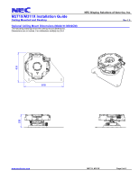
Ceiling Mounted and Desktop, Diagrams and Distance Charts, Ceiling Mounted, Desktop, Distance Chart - projector ceiling mount
 |
View all NEC NP-M311X manuals
Add to My Manuals
Save this manual to your list of manuals |
Page 2 highlights
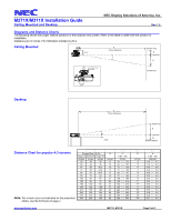
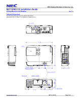
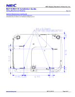
M271X/M311X Installation Guide Ceiling Mounted and Desktop NEC Display Solutions of America, Inc. Rev 1.0 Diagrams and Distance Charts The following shows the proper relative positions of the projector and screen. Refer to the table to determine the position of installation. Distances are in inches. For millimeters multiply by 25.4. Ceiling Mounted 4.56" 5.17" C Throw Distance Screen Top D Lens Ctr B Lens Offset From Mount Pipe Screen Ctr 2.79 Desktop C Throw Distance 2.22" Screen Ctr B Lens Ctr D Screen Bottom Distance Chart for popular 4:3 screens Note: For screen sizes not indicated on the projection tables, use the formulas on page 1. Screen Size (16:10) Diagonal Width(W) Height (H) inches inches inches 30 24 18 60 48 36 67 54 40.2 72 58 43.2 84 67 50.4 90 72 54 100 80 60 120 96 72 150 120 90 180 144 108 210 168 126 240 192 144 270 216 162 300 240 180 B inches 6 12 14 15 17 19 21 25 31 37 43 49 56 62 C w ide - tele inches 31 - 53 64 - 107 71 - 120 77 - 129 90 - 151 97 - 162 108 - 180 129 - 216 162 - 270 195 - 325 228 - 379 261 - 434 293 - 488 326 - 543 www.necdisplay.com M271X, M311X D inches -3 -6 -6 -7 -8 -8 -9 -11 -14 -17 -20 -22 -25 -28 α w ide - tele degrees 11.3 - 6.7 11.0 - 6.6 10.9 - 6.6 10.9 - 6.6 10.9 - 6.6 10.9 - 6.6 10.9 - 6.5 10.8 - 6.5 10.8 - 6.5 10.8 - 6.5 10.8 - 6.5 10.8 - 6.5 10.8 - 6.5 10.7 - 6.5 Page 2 of 6
-
 1
1 -
 2
2 -
 3
3 -
 4
4 -
 5
5 -
 6
6
 |
 |
