NEC NP-V260X PC Control Connectors and Cables - Page 1
NEC NP-V260X Manual
 |
UPC - 805736036596
View all NEC NP-V260X manuals
Add to My Manuals
Save this manual to your list of manuals |
Page 1 highlights
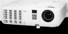
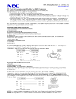
NEC Display Solutions of America, Inc. www.necdisplay.com PC Control Connectors and Cables for NEC Projectors v4.4 NEC labels the connector for RS232C serial communication the "PC Control" port. This PC Control port can be used for the following functions: • Communication from an AMX, Crestron or Extron control system. • Communication from a PC using the NEC PC Control Utility for basic projector control. • Communication from a PC using the NEC Geometric Correction Tool for adjusting a projector to display an image on a cylindrical, spherical or corner screen. • Communication from a PC using the NEC Image Express Utility to send images to the projector for presentations as well as basic projector control, projector lamp and error status or asset management. (These functions can also be accomplished via LAN or USB with models that have a network interface, optional network PC card or USB interface) NEC uses two types of connectors for the PC Control port, a D-Sub 9pin for larger projectors and a mini-DIN 8pin for smaller projectors due to space constraints on those models. Models with D-Sub 9Pin PC Control port: M260X/M260W/M300X/M300W/M300XS/M300WS V260/V260X/V300X NP110/BP115/NP215/NP216 NP300/ NP400/NP500/NP500W/NP500WS/NP600/NP600S, NP310/NP410/NP410W/NP510/NP510W/NP510W/NP610/NP610S NP905/NP901W NP1000/NP2000, NP1150/NP2150/NP3150/NP3151W, NP1250/NP2250W/NP3250/NP3250W, NP1200/NP2200 NP4000/4001, NP4100/4100W P350X/P350W/P420X PA500X/PA500U/PA550W/PA600X VT770/VT800 U300X/U310W A standard D-Sub 9P female to D-Sub 9P female "Null Modem" or "Cross" cable can be obtained at a local computer or electronics store. A "Straight Through" cable will not work. If you prefer to assemble your own cable, you can use the pin out information below. To TxD of PC D-Sub 9P Female D-Sub 9P Female To RxD of PC To GND of PC RxD Pin 2 Pin 2 RxD TxD Pin 3 Pin 3 TxD 12 3 45 GND Pin 5 Pin 5 GND Pin 7 Pin 7 Pin 8 Pin 8 *Tie Pin 7 & 8 together at both ends of the cable if desired 67 8 9 To RTS of PC To CTS of PC Models with mini-DIN 8Pin PC Control port: LT30/LT35 LT240/LT260/2LT45/LT265 NP40/NP50/NP60, NP41/NP61/NP62, NP43/NP64 VT37/VT47/VT470/VT570/VT575/VT670/VT676/VT48/VT480/VT580/VT49/VT490/VT491/VT590/VT595/VT695/VT700 WT600/WT610E A cable can be purchased from NEC using the following part number. (Service P/N: CA03DE) If you prefer to assemble your own cable, use the pin out information below and the following tips. Soldering a mini-DIN connector can be tedious. To simplify the cable assembly, you can purchase a MAC or Sun type keyboard/mouse cable (mini-DIN 8P) at a local computer store. Cut a DIN connector from one end and attach a D-Sub 9P Female to that end using the pin out below. D-Sub 9P Female mini-DIN 8P Male 87 6 54 3 RxD Pin 2 Pin 7 TxD 21 TxD Pin 3 Pin 1 RxD GND Pin 5 Pin 7 Pin 8 *Tie Pin 7 & 8 together if desired Pin 4 GND Note: Do not confuse Pins 1 & 2 on the mini-DIN 8P connector. Pin 1 is below Pins 3 & 4 which are offset to one side of the connector. NOTE1: It is recommended to set the projector to "Idle Mode" in the Setup menu for best Power ON response. NOTE2: For long cable runs it is recommended to set communication speed to 9600 bps in the Setup menu.
-
 1
1
 |
 |