NEC PX-60XM5A 60XM5 start up manual - Page 7
Creating a video wall, Cable Management - 60 plasma display
 |
View all NEC PX-60XM5A manuals
Add to My Manuals
Save this manual to your list of manuals |
Page 7 highlights
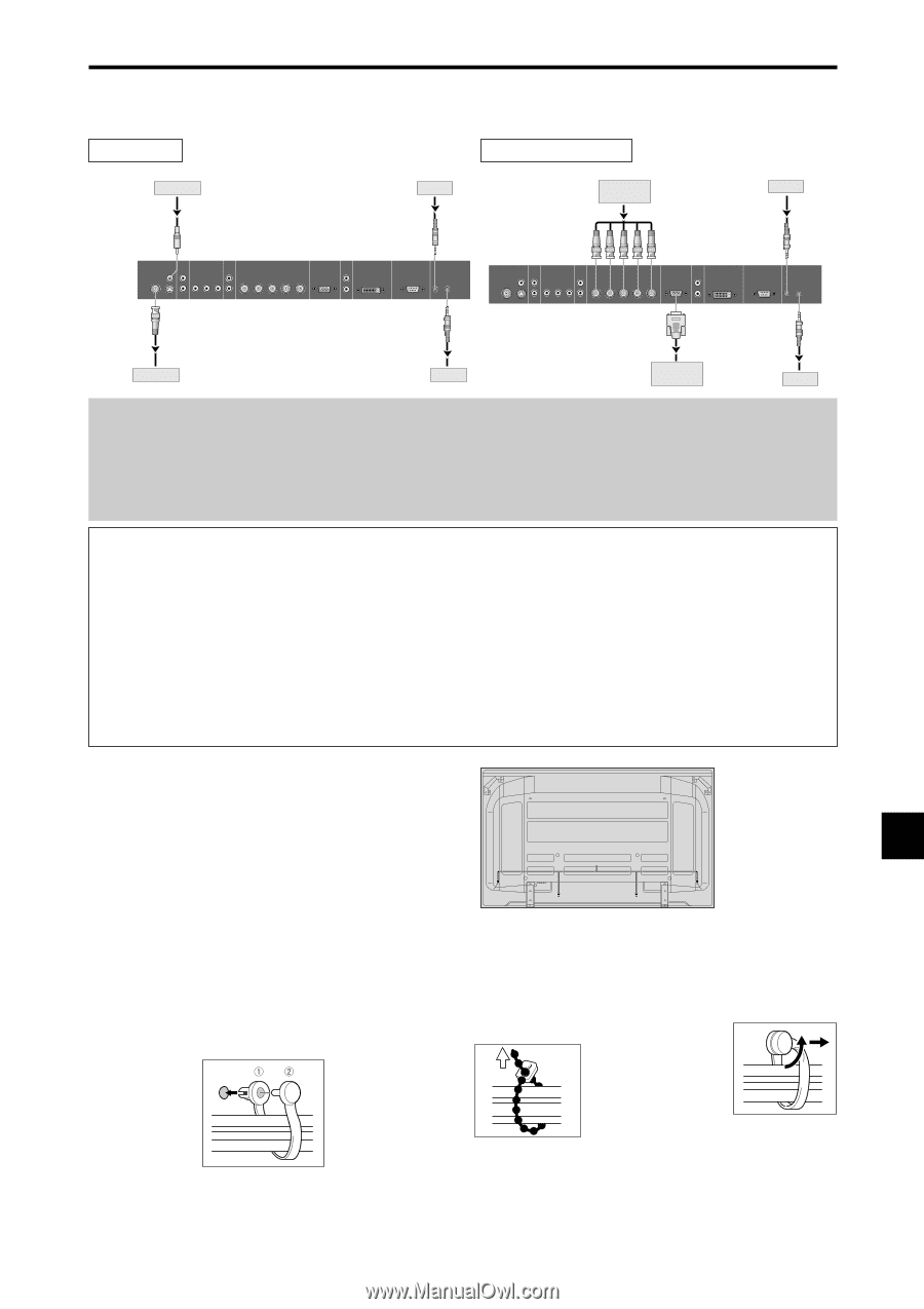
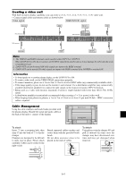
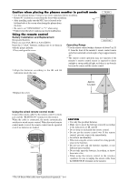
Creating a video wall With built-in matrix display capability, you can create a (2ן2, 3ן3, 4ן4, 5ן5, 5ן1, 1ן5) video wall. • Connect signal cables and remote cables as shown below. Video signal RGB/DVD/HD signal VIDEO Signal IN Remote control IN RGB signal/ DVD/HD signal IN Remote control IN RCA phono plug VIDEO 2 AUDIO 1 R DVD1 / HD1 AUDIO 2 R RGB2 / DVD2 / HD2 1(IN/OUT) 3 Y Cb/Pb Cr/Pr R/Cr/Pr G/Y B/Cb/Pb HD VD L (MONO) L (MONO) RGB 1 (IN/OUT) AUDIO 3 R RGB 3 DV I ( Digital RGB ) L (MONO) EXTERNAL CONTROL REMOTE IN OUT BNC connector BNC connector VIDEO 2 AUDIO 1 R DVD1 / HD1 AUDIO 2 R RGB2 / DVD2 / HD2 1(IN/OUT) 3 Y Cb/Pb Cr/Pr R/Cr/Pr G/Y B/Cb/Pb HD VD L (MONO) L (MONO) RGB 1 (IN/OUT) AUDIO 3 R RGB 3 DV I ( Digital RGB ) L (MONO) EXTERNAL CONTROL REMOTE IN OUT OUT VIDEO Signal OUT Remote control OUT RGB signal/ DVD/HD signal OUT Remote control Note: 1. The VIDEO1 and RGB1 terminals can be used for either INPUT or OUTPUT. When LOOP OUT is ON, do not connect an OUTPUT signal from another unit as it may damage the other unit due to an extraordinary load. 2. LOOP OUT can not be turned ON while signals are input to the RGB1 terminal. 3. LOOP OUT can be turned ON while signals are input to the RGB1 terminal if the POWER is switched ON. Information • To loop signals out to another plasma display, set the LOOP OUT to ON. • To create a video wall, set the VIDEO WALL menu items properly. • To connect monitors, please use a 1 m to 2 m (3.3 feet to 6.6 feet) BNC cable (any commercially available cable). • If the image quality is poor, do not use the monitor's out terminal. Use a distribution amplifier (any commercially available distribution amplifier) to connect the split signals to the respective monitor INPUT terminals. • Being used as a video wall function, maximaly 4-screen is rough-standard with lower than 1024ן768, 60 Hz signal. • A distribution amplifier is particularly recommended when creating a 3ן3 (or greater) video wall. • When looping from plasma to plasma, a 1 m to 2 m (3.3 feet to 6.6 feet) 15 pin male D-Sub - 5BNC conversion cable is required. Cable Management Using the cable clampers and beads bands provided with the plasma display; Bundle the signal and audio cables at the back of the unit to connect to the display. Back of the unit mounting holes To attach Insert q into a mounting hole, then snap w into the back of q to fix the clamper. Clampers are designed to be difficult to undo once in place. Please attach carefully. Cables can be routed to the right or left. Bunch separated cables together and secure them with the provided beads bands. Do not allow excessive stress to be placed on the ends of cables. To detach Using pliers, twist the clamper 90° and pull it outward. In some cases the clamper may have deteriorated over time and may get damaged when removed. En-5
-
 1
1 -
 2
2 -
 3
3 -
 4
4 -
 5
5 -
 6
6 -
 7
7 -
 8
8 -
 9
9 -
 10
10 -
 11
11 -
 12
12 -
13
-
14
-
15
-
16
-
17
-
18
-
19
-
20
-
21
-
22
-
23
-
24
-
25
-
26
-
27
-
28
-
29
-
30
-
31
-
32
-
33
-
34
-
35
-
36
-
37
-
38
-
39
-
40
-
41
-
42
-
43
-
44
-
45
-
46
-
47
-
48
-
49
-
50
-
51
-
52
-
53
-
54
-
55
-
56
-
57
-
58
-
59
-
60
-
61
-
62
-
63
-
64
-
65
-
66
-
67
-
68
 |
 |