Nady PMX-1600 Owners Manual - Page 8
Master Input / Output
 |
View all Nady PMX-1600 manuals
Add to My Manuals
Save this manual to your list of manuals |
Page 8 highlights
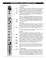
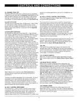
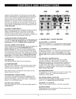
CONTROLS AND CONNECTIONS (34) (36) (32) outputs for easy monitoring. The Group can be a very useful feature if used effectively. For stage applications the Group mix can be sent to a monitor amplifier so the performers will only hear the audio that is not already loud enough on stage. Subgroups are commonly used as a mixing aid both live and in the studio. For example, you can combine the outputs from all drum channels onto just the two Group faders. This submix can also be added to the Main/Master mix by depressing the Group to Main Switch (23). (23) GROUP TO MAIN SWITCH When this push-button switch is depressed, the Group submix is added to the Main/Master bus. This allows controlling the combined volume of multiple channels with only two faders, which can be useful when mixing a vocal quartet or multiple mics for grouped instruments like percussion or drum kits. (30) (31) (35) (33) (24) MASTER STEREO VOLUME FADERS This adjusts the final level of the Master Left & Right signals, that are sent to the Main (36), Headphone (33), and Control Room (34) Outputs and also to the Speaker Stereo Outputs (37). (25) DUAL CHANNEL LED VU METER These 10-stage stereo output LED meter displays will display the relative output level of the Left and Right Main (36) and Speaker Outputs (37). They can be used to maintain proper levels in the master mix. The top red Peak LED will light when the powered output signal is just below clipping. It is acceptable if the red LED lights occasionally. If the red LED lights more than occasionally, you should turn down the Master Stereo Volume Faders (24) to avoid audible distortion and clipping, which can cause damage to your speakers and even the internal amplifier. (26) POWER LED This LED will illuminate when the unit is switched on. (27) PHANTOM POWER When this switch is depressed, +48V of phantom power will be supplied to the mic channels. The yellow LED will illuminate when the switch is depressed to ON. 4. MASTER INPUT / OUTPUT SECTION (30) AUX SEND 1 & 2 OUTPUTS These mono unbalanced 1/4" jacks output the auxiliary signals which can be adjusted by the Aux Send 1 & 2 Level Controls (14). (31) AUX RETURN 1 & 2 INPUTS These mono unbalanced 1/4" jacks enable convenient inputs to the Master/Main busses. If you connect a signal to the return jacks, the signal will be routed to the Aux Return 1 or 2 Level Controls (16) and then mixed into the left and right Master/Main bus. (32) TAPE INPUT / RECORD OUTPUT The Left and Right Tape Input RCA jacks allow cassette recorders, CD players, or MP3 players to be added to the Master/Main mix outputs. The input signals can be adjusted by the Tape Level Control (29). The Record Output RCA jacks provide a stereo signal output to recording devices, home audio equipment, or external amplifiers. These outputs are post Master Stereo Volume Faders (24). [Note: When turning on the Phantom Power switch, turn the Master Volumes to minimum.] (28) HEADPHONE / CONTROL ROOM The volume control adjusts the level of the Headphone and Control Room Outputs. The push-button selector switch will determine which signal is sent to these outputs - depressed for Group 1 & 2, out for Master Stereo. (33) HEADPHONE OUTPUT The Headphone 1/4" stereo output can be used to monitor either the Master or Group mix. It will power headphones with impedances of 8Ω or greater. (34) CONTROL ROOM L-R OUTPUTS These separate Left and Right 1/4" jacks output the line level signals from the Headphone/Control Room (28). (29) TAPE LEVEL CONTROL This control adjusts the level of the Tape Input signal applied to Master/Main bus. (35) GROUP 1 & 2 OUTPUTS These 1/4" jacks output the Group 1 and 2 line level signals. (36) MAIN OUTPUTS These balanced XLR and unbalanced 1/4" jacks output the final Master/Main Mix line level signals. 8
-
 1
1 -
2
-
 3
3 -
 4
4 -
 5
5 -
 6
6 -
 7
7 -
 8
8 -
 9
9 -
 10
10 -
 11
11 -
 12
12
 |
 |
