Nady SRM-10X Manual - Page 10
c. Monitor Function and Operation, d. Power Switches - srm 10
 |
View all Nady SRM-10X manuals
Add to My Manuals
Save this manual to your list of manuals |
Page 10 highlights
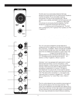
CONTROLS AND CONNECTIONS (31) (32) (34) (33) (35) The SRM-10X allows you to monitor the Master Mix. The signal level is adjusted with the Headphone/Control Room level (39) and routed to both the Control Room (22) and Phones (21) output. The Control Room Output (22) can be connected to an amp to power stereo control room (or other) monitor speakers and is 1/4" stereo jack. Both Control Room (22) and Phones (21) outputs are wired: Tip = left signal, ring = right signal, sleeve = ground. (36) (37) (38) (39) c. Monitor Function and Operation (38) AUX TO METER AND CTRL R/PHONES (42) AFL SWITCH (22) CONTROL ROOM OUTPUT (21) PHONES OUTPUT (39) PHONES/CONTROL ROOM CONTROL (40) (41) (42) d. Power Switches (43) AC POWER IN SOCKET (44) MAIN POWER SWITCH (35) POWER ON LED INDICATOR Once the external PSU is connected to the AC Power In socket (43) and then to the AC power source, you may switch on your mixer with the Power On switch (44). The Power "ON" LED (35) will light up. Allow 1 minute after powering up for the system to reach equilibrium before setting inputs gains and other levels. (33) PHANTOM POWER SWITCH (34) PHANTOM POWER ON LED INDICATOR When using condenser mics, +48VDC can be switched globally on or off to the XLR mic inputs for all mono channels (also see MONO INPUT SECTION, MIC INPUTS). When this switch is in the "ON" position, the Phantom Power On LED Indicator (34) will light , and +48VDC will be provided between pins 2 and 3 on all the mono Mic input XLR connectors. If you don't need phantom power, be sure to turn this switch to the "OFF" position. [Note: It is safe to connect balanced dynamic mics or line level devices even if this switch is on, but connecting unbalanced devices or devices whose transformers are center-grounded will cause hum or malfunctions. Shorting the +48VDC can also damage your mixer. Also, mute the Monitor/PA speakers when turning the phantom power on or off.] Depressing the AUX TO METER AND CTRL R/PHONES button (38) allows the Aux Send output signal to be directly monitored by the Meter Display and the Control Room / Headphone outputs. This button overrides the AFL switch. (44) (43) [Note: When this button is depressed, all PFL switches should be in the off (up) position] When depressing the AFL switch (42), the Meter Display and Control Room/Headphone outputs will monitor the Mono output signal. BACK PANEL 10
-
 1
1 -
2
-
3
-
4
-
 5
5 -
 6
6 -
 7
7 -
 8
8 -
 9
9 -
 10
10 -
 11
11 -
 12
12 -
 13
13 -
 14
14 -
 15
15 -
16
 |
 |
