Netgear APS1000W Installation Guide - Page 1
Netgear APS1000W Manual
 |
View all Netgear APS1000W manuals
Add to My Manuals
Save this manual to your list of manuals |
Page 1 highlights
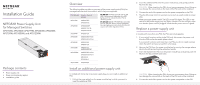
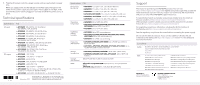
Installation Guide NETGEAR Power Supply Unit for Managed Switches APS150W, APS250W, APS299W, APS550W, APS600W, APS750W, APS1000W, and APS1200W Package contents • Power supply unit • Power cord (varies by region) • Installation guide Overview The following table provides an overview of the power supply units (PSUs) for managed switches and the models in which they are supported. PSU Model Used in Switch Model APS150W M4300-28G M4300-52G APS250W M4300-8X8F M4300-12X12F M4300-24X24F AC OK LED. All PSUs provide one AC OK LED. During normal operation, this LED lights green to indicate that the PSU is receiving power. DC OK LED. Model APS150W also provides one DC OK LED. During normal operation, this LED lights green to indicate that the DC outputs are within regulation limits. APS299W M4300-16X APS550W M4300-28G-POE+ M4300-52G-POE+ APS600W M4300-96X M4300-16X APS750W M4500-32C M4500-48XF8C APS1000W M4300-28G-POE+ M4300-52G-POE+ M6100-3S RPS4000v2 APS1200W M4300-96X Install an additional power supply unit In models with more than one power supply bay, you can install an additional PSU. 1. Pull out the cover plate from the power module bay in which you want to insert the additional PSU. 2. Insert the additional PSU into the power module bay, and gently push the PSU into the bay. CAUTION: When inserting the PSU, do not use unnecessary force. Doing so can damage the connectors on the back of the PSU and on the midplane. 3. Connect the end of the power cord to the power receptacle on the PSU. 4. Plug the AC power cord into a power source such as a wall socket or power strip. When you apply power, the AC OK LED on the PSU lights. The LED on the switch for the power supply bay also lights. If these LEDs do not light, make sure that the power cord is plugged in and that the power source is good. Replace a power supply unit In models with more than one PSU, the PSUs are hot-pluggable. 1. If your switch functions with a single PSU only, disconnect the power cord from the PSU and let the switch power down. If your switch functions with more than one PSU, you do not need to power down the switch and you can perform a hot swap. 2. Remove the PSU from the power module bay by moving the orange release latch to the left and pulling the extraction handle. 3. Insert the replacement PSU into the power module bay, and gently push the PSU into the bay until the latch locks. CAUTION: When inserting the PSU, do not use unnecessary force. Doing so can damage the connectors on the back of the PSU and on the midplane. 4. Connect the end of the power cord to the power receptacle on the PSU.
-
 1
1 -
 2
2
 |
 |