Netgear EN308TC EN308TC Installation Guide - Page 9
Cascade the Hub Using the 10BASE-T Ports, button on each hub.
 |
View all Netgear EN308TC manuals
Add to My Manuals
Save this manual to your list of manuals |
Page 9 highlights
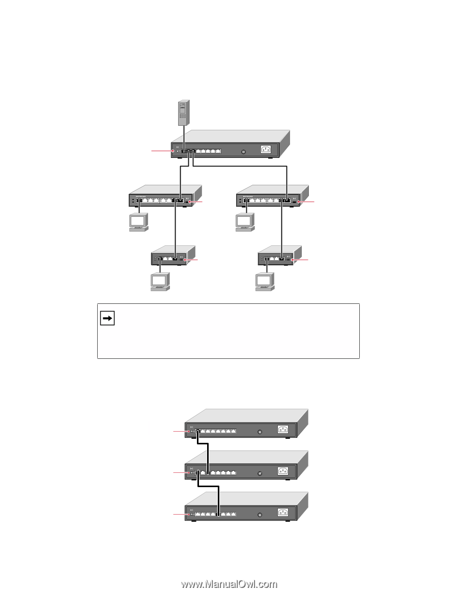
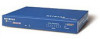
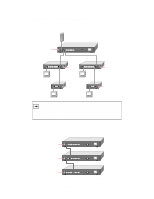
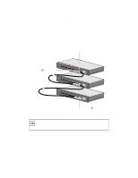
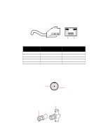
Cascade the Hub Using the 10BASE-T Ports The following illustration shows cascading hubs together in a hierarchical star through the 10BASE-T ports and indicates the setting of the Normal/Uplink push button on each hub. Normal Model EN308TC hub 1 100M 10M Normal/Uplink On = Link Blinking = Activity 8 7 6 5 4 3 2 1 BNC 100-240 VAC, 50-60Hz 0.2A max. Model EN108 hub 2 10 BASE-T HUB EN108TP Pwr Col 1 2 3 4 5 6 7 8 Model EN108 hub Uplink 3 Pwr Col 1 10 BASE-T HUB EN108TP 2 3 4 5 6 7 8 Uplink Model EN104 hub 4 Uplink Model EN104 hub 5 Uplink A B 9122FA Note: Ethernet specifications limit the number of hubs with twisted pair links in any communication path to five, as shown in the example. When PC "A" communicates with PC "B," the communication path goes from hub 4 to hub 2, to hub 1, to hub 3, and then to hub 5 (or five paths). The following illustration shows cascading Model EN308TC hubs together daisy-chain style. Refer to the illustration for setting the Normal/Uplink push button on each hub. Normal 100M 10M Normal/Uplink On = Link Blinking = Activity 8 7 6 5 4 3 2 1 BNC 100-240 VAC, 50-60Hz 0.2A max. Uplink 100M 10M Normal/Uplink On = Link Blinking = Activity 8 7 6 5 4 3 2 1 BNC 100-240 VAC, 50-60Hz 0.2A max. Uplink 100M 10M Normal/Uplink On = Link Blinking = Activity 8 7 6 5 4 3 2 1 BNC 100-240 VAC, 50-60Hz 0.2A max. 9123FA Model EN308TC Ethernet Hub Installation Guide
-
 1
1 -
2
-
3
-
 4
4 -
 5
5 -
 6
6 -
 7
7 -
 8
8 -
 9
9 -
 10
10 -
 11
11 -
 12
12 -
 13
13 -
 14
14 -
15
-
16
-
17
 |
 |