Netgear FE108 Installation Guide - Page 38
Twisted Pair Cables, the instructions in Installation
 |
UPC - 606449000894
View all Netgear FE108 manuals
Add to My Manuals
Save this manual to your list of manuals |
Page 38 highlights
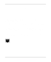
Installation Guide for the Model FE104 and Model FE108 Fast Ethernet Hubs Twisted Pair Cables For two devices to communicate, the transmitter of each device must be connected to the receiver of the other device. The crossover function is usually implemented internally as part of the circuitry in the device. Computers and workstation adapter cards are usually media-dependent interface ports, called MDI or uplink ports. Most repeaters and switch ports are configured as media-dependent interfaces with built-in crossover ports, called MDI-X or normal ports. Refer to the instructions in Chapter 3, "Installation," for appropriate cable use and connection. Figure C-1 illustrates straight-through twisted pair cable connections, and Figure C-2 illustrates crossover twisted pair cable connections. 1 Tx 2 1 3 Rx 6 1 Rx 2 2 3 Tx 6 7181 Key: 1 = Uplink or MDI port 2 = Normal or MDI-X port Figure C-1. Straight-through twisted pair cable 1 Rx 2 1 3 Tx 6 1 Rx 2 2 3 6 Tx Key: 1 = Normal or MDI-X port 2 = Normal or MDI-X port Figure C-2. Crossover twisted pair cable C-4 7182 Fast Ethernet and Cabling Guidelines
-
 1
1 -
2
-
3
-
4
-
5
-
6
-
7
-
8
-
9
-
10
-
11
-
12
-
13
-
14
-
15
-
16
-
17
-
18
-
19
-
20
-
21
-
22
-
23
-
24
-
25
-
26
-
27
-
28
-
29
-
30
-
31
-
32
-
 33
33 -
 34
34 -
 35
35 -
 36
36 -
 37
37 -
 38
38 -
 39
39 -
 40
40 -
 41
41 -
 42
42 -
 43
43 -
44
 |
 |