Netgear FR114W FR114W Reference Manual - Page 28
The Firewall’s Rear Panel, Connecting the Firewall, Parallel Printer port FR114P and FM114P only - fr114p printer install
 |
View all Netgear FR114W manuals
Add to My Manuals
Save this manual to your list of manuals |
Page 28 highlights
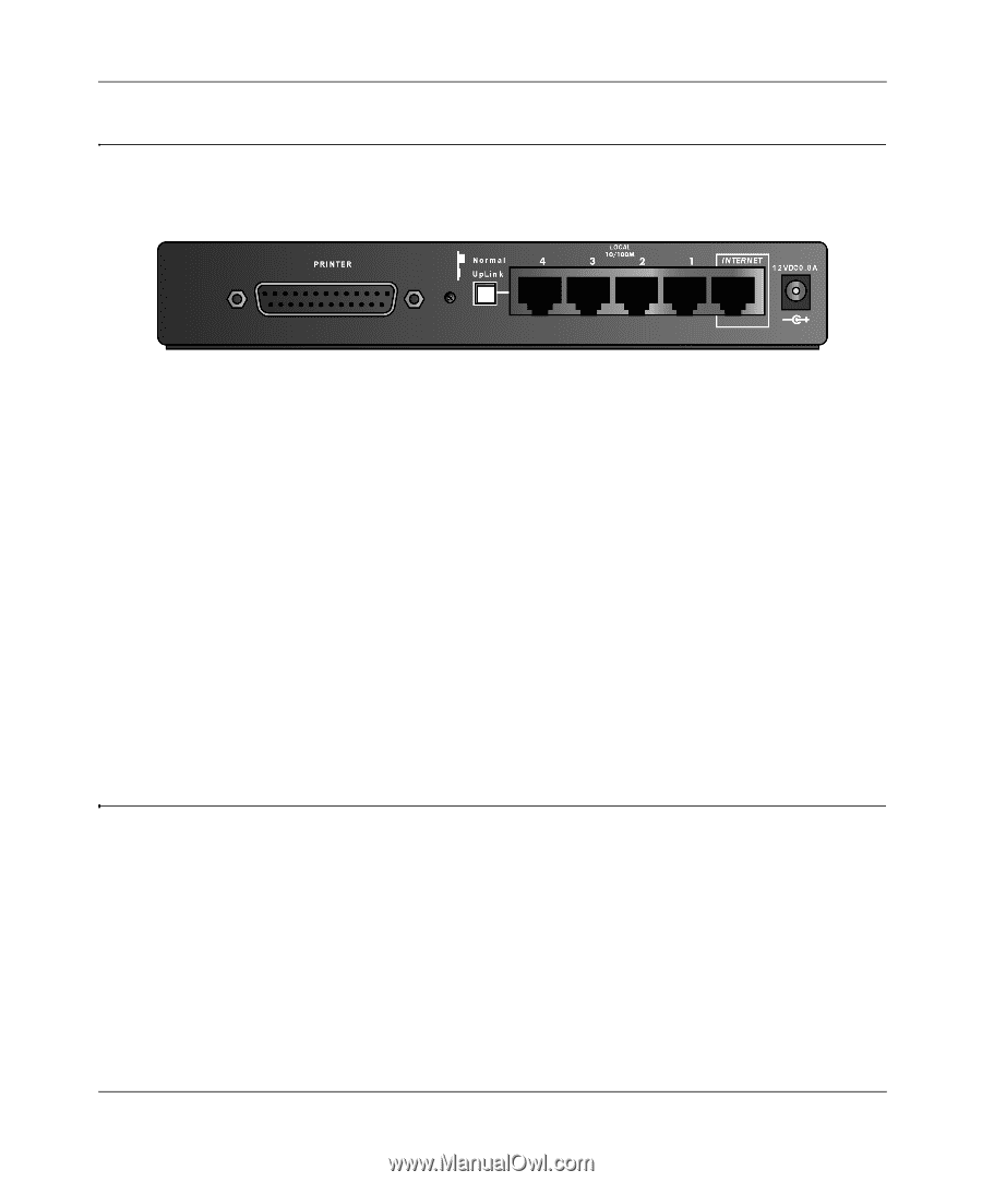
Reference Manual for the Model FR114P, FR114W and FM114P Cable/DSL ProSafe Firewall The Firewall's Rear Panel The rear panel of the NETGEAR ProSafe Firewall contains port connections. The FR114P Firewall rear panel is shown in Figure 2-2 Figure 2-2. FR114P Rear Panel The rear panel contains the following features: • AC power adapter outlet • Internet (WAN) Ethernet port for connecting the firewall to a cable or DSL modem • Four Local (LAN) Ethernet ports for connecting the firewall to the local PCs • Uplink switch for converting LAN port 4 to uplink (crossover) wiring • Factory Default Reset pushbutton • Parallel Printer port (FR114P and FM114P only) • Wireless adapter slot (FR114W only) • Wireless antenna (FM114P only) Connecting the Firewall Before using your firewall, you need to do the following: • Connect your cable or DSL modem to the Internet port of the firewall (described next. • Connect your local Ethernet network to the Local port(s) of the firewall (see page 2-5). • Prepare your wireless devices. • Install your wireless adapter card (FR114W only) • Connect the power adapter (see page 2-6) Note: The Resource CD included with your firewall contains an animated Connection Guide to help you through this procedure. 2-4 Setting Up the Hardware
-
 1
1 -
2
-
3
-
4
-
5
-
6
-
7
-
8
-
9
-
10
-
11
-
12
-
13
-
14
-
15
-
16
-
17
-
18
-
19
-
20
-
21
-
22
-
 23
23 -
 24
24 -
 25
25 -
 26
26 -
 27
27 -
 28
28 -
 29
29 -
 30
30 -
 31
31 -
 32
32 -
 33
33 -
34
-
35
-
36
-
37
-
38
-
39
-
40
-
41
-
42
-
43
-
44
-
45
-
46
-
47
-
48
-
49
-
50
-
51
-
52
-
53
-
54
-
55
-
56
-
57
-
58
-
59
-
60
-
61
-
62
-
63
-
64
-
65
-
66
-
67
-
68
-
69
-
70
-
71
-
72
-
73
-
74
-
75
-
76
-
77
-
78
-
79
-
80
-
81
-
82
-
83
-
84
-
85
-
86
-
87
-
88
-
89
-
90
-
91
-
92
-
93
-
94
-
95
-
96
-
97
-
98
-
99
-
100
-
101
-
102
-
103
-
104
-
105
-
106
-
107
-
108
-
109
-
110
-
111
-
112
-
113
-
114
-
115
-
116
-
117
-
118
-
119
-
120
-
121
-
122
-
123
-
124
-
125
-
126
-
127
-
128
-
129
-
130
-
131
-
132
-
133
-
134
-
135
-
136
-
137
-
138
-
139
-
140
-
141
-
142
-
143
-
144
-
145
-
146
-
147
-
148
-
149
-
150
 |
 |