Netgear FSM7328PS FSM7328PS Hardware manual
Netgear FSM7328PS - ProSafe 24 Port 10/100 L3 Managed Stackable Switch Manual
 |
UPC - 606449051810
View all Netgear FSM7328PS manuals
Add to My Manuals
Save this manual to your list of manuals |
Netgear FSM7328PS manual content summary:
- Netgear FSM7328PS | FSM7328PS Hardware manual - Page 1
Managed Stackable Layer 3 Fast Ethernet Switches Hardware Installation Guide Models FSM7328S, FSM7328PS, FSM7352S, and FSM7352PS NETGEAR, Inc. 4500 Great America Parkway Santa Clara, CA 95054 USA 202-10256-01 May 2007 - Netgear FSM7328PS | FSM7328PS Hardware manual - Page 2
Netgear Logo, the Gear Guy, Everybody's connecting, and ProSafe are trademarks or registered trademark of Netgear certified that the NETGEAR Model FSM7328S Managed Fast Ethernet instructions. It is hereby certified that the NETGEAR Model FSM7328PS user may be required to take corrective - Netgear FSM7328PS | FSM7328PS Hardware manual - Page 3
installation. This equipment generates, uses, and can radiate radio frequency energy and, if not installed and used in accordance with the instructions . Cet appareil numérique (ProSafe 24-Port 10/100 LE managed Stackable Switch with 4 Gigabit Ports and PoE FSM7328PS) respecte les limites de bruits - Netgear FSM7328PS | FSM7328PS Hardware manual - Page 4
Support Information Card that shipped with your Managed Stackable Layer 3 Fast Ethernet Switch. World Wide Web NETGEAR maintains a World Wide Web home page that you can access at the universal resource locator (URL) http://www.netgear Publication Version Number FSM7328S, FSM7328PS, FSM7352S, and - Netgear FSM7328PS | FSM7328PS Hardware manual - Page 5
and LEDs 2-2 FSM7328S Rear Panel 2-3 FSM7328PS Front Panel and LEDs 2-4 FSM7328PS Rear Panel 2-6 FSM7352S Front Panel and LEDs 2-6 FSM7352S Rear Panel 2-7 FSM7352PS Front Panel and LEDs 2-8 FSM7352PS Rear Panel 2-10 Safety Instructions ...2-10 Chapter 3 Hardware Installation Package Contents - Netgear FSM7328PS | FSM7328PS Hardware manual - Page 6
Connecting a Console to the Switch 3-9 Chapter 4 Troubleshooting Troubleshooting Chart 4-1 Additional Troubleshooting Suggestions 4-2 Appendix A Technical Specifications Appendix B Default Configuration Settings vi Publication Version 1.0, May 2007 - Netgear FSM7328PS | FSM7328PS Hardware manual - Page 7
Manual The FSM7328S,FSM7328PS, FSM7352S, and FSM7352PS Managed Stackable Layer 3 Fast Ethernet Switches Hardware Installation Guide contains information for set up and management of the NETGEAR FSM7328S, FSM7328PS , books, CDs, URL names User input This guide uses the following formats to highlight - Netgear FSM7328PS | FSM7328PS Hardware manual - Page 8
3 Fast Ethernet Switches Hardware Installation Guide This manual is written according to these specifications: Table 1-2. Manual Scope Product version Manual publication date • ProSafe 24-Port 10/100 LE managed Stackable Switch with 4 Gigabit Ports FSM7328S • ProSafe 24-Port 10/100 LE managed - Netgear FSM7328PS | FSM7328PS Hardware manual - Page 9
This guide describes hardware installation and basic troubleshooting for the following NETGEAR switches: • ProSafe 24-Port 10/100 LE managed Stackable Switch with 4 Gigabit Ports FSM7328S • ProSafe 24-Port 10/100 LE managed Stackable Switch with 4 Gigabit Ports and PoE FSM7328PS • ProSafe 48-Port 10 - Netgear FSM7328PS | FSM7328PS Hardware manual - Page 10
Managed Stackable Layer 3 Fast Ethernet Switches Hardware Installation Guide FSM7328S Front Panel and LEDs The following figure shows the front panel of the FSM7328S. The front panel contains LEDs, RJ-45 jacks, SFP module bays, stacking ports, and a console port. LEDs Figure 2-1 RJ-45 jacks SFP - Netgear FSM7328PS | FSM7328PS Hardware manual - Page 11
Managed Stackable Layer 3 Fast Ethernet Switches Hardware Installation Guide Table 2-1. LED Descriptions for FSM7328S (continued) LED Description 10/100/1000M ports two LEDs per port Link/ACT LED • Off: No 10/100/1000 Mbps link is established on the port. • Solid green: A valid 1,000 Mbps link - Netgear FSM7328PS | FSM7328PS Hardware manual - Page 12
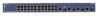
Managed Stackable Layer 3 Fast Ethernet Switches Hardware Installation Guide FSM7328PS Front Panel and LEDs The following figure shows the front panel of the FSM7328PS. The front panel contains LEDs, RJ-45 jacks, SFP module bays, and stacking ports. ID PoE 1 L/A 3 5 7 9 11 13 15 17 19 - Netgear FSM7328PS | FSM7328PS Hardware manual - Page 13
Stackable Layer 3 Fast Ethernet Switches Hardware Installation Guide Table 2-2. LED Descriptions for FSM7328PS (continued) LED Description 10/100M ports two LEDs per port Link/ACT/SPD LED (on the right) • Off: No 10/100 Mbps link is established on the port. • Solid green: A valid 100 Mbps link - Netgear FSM7328PS | FSM7328PS Hardware manual - Page 14
Stackable Layer 3 Fast Ethernet Switches Hardware Installation Guide FSM7328PS Rear Panel The rear panel has a Console port, redundant power supply (RPS) connector, and a standard AC power receptacle for the supplied power cord. Console port Power receptacle Console RPS Connector Figure - Netgear FSM7328PS | FSM7328PS Hardware manual - Page 15
Layer 3 Fast Ethernet Switches Hardware Installation Guide Table 2-3. FSM7352S LED Description (continued ports One LED per port Link/ACT/SPD LED • Off: No 10/100 Mbps link is established on the port. • Solid green: A valid 100 Mbps link is established on the port. • Blinking green: The port - Netgear FSM7328PS | FSM7328PS Hardware manual - Page 16
Managed Stackable Layer 3 Fast Ethernet Switches Hardware Installation Guide FSM7352PS Front Panel and LEDs The following figure shows the front panel of the FSM7352PS. The front panel contains LEDs, RJ-45 jacks, SFP module bays, and stacking ports. The console port is on the rear panel. FSM7352PS - Netgear FSM7328PS | FSM7328PS Hardware manual - Page 17
Managed Stackable Layer 3 Fast Ethernet Switches Hardware Installation Guide Table 2-4. FSM7352S LED Description (continued) 10/100M Ports One LED per port Right LED shows Link, Activity, and Speed • Off: No 10/100 Mbps link is established on the port. • Solid green: A valid 100Mbps link is - Netgear FSM7328PS | FSM7328PS Hardware manual - Page 18
Installation Guide FSM7352PS Rear Panel The rear panel has a console port, a redundant power supply connector, and a standard AC power receptacle for the supplied power cord. Console port FSM7352PS Back Panel Redundant power supply Power receptacle Figure 2-8 Safety Instructions service - Netgear FSM7328PS | FSM7328PS Hardware manual - Page 19
system components, and never operate the product in a wet environment. If the system gets wet, see the appropriate section in your troubleshooting guide or contact your trained service provider. • Do not push any objects into the openings of your system. Doing so can cause fire or electric shock by - Netgear FSM7328PS | FSM7328PS Hardware manual - Page 20
Managed Stackable Layer 3 Fast Ethernet Switches Hardware Installation Guide • Observe extension cable and power strip ratings. Make sure that the total ampere rating of all products plugged into the extension cable or power strip - Netgear FSM7328PS | FSM7328PS Hardware manual - Page 21
- Configuration software - Documentation including the Command Line Interface Reference for the ProSafe 7300S Series Layer-3 Stackable Switches, the Administration Manual for the ProSafe 7300S Series Layer-3 Stackable Switches, the Quick Install Guide, and this Hardware Installation Guide • Warranty - Netgear FSM7328PS | FSM7328PS Hardware manual - Page 22
Stackable Layer 3 Fast Ethernet Switches Hardware Installation Guide Protecting Against Electrostatic Discharge Warning: Static of the boxes to make sure that all items are present before beginning the installation. 1. Place the container on a clean flat surface and cut all straps securing - Netgear FSM7328PS | FSM7328PS Hardware manual - Page 23
Managed Stackable Layer 3 Fast Ethernet Switches Hardware Installation Guide 4. Make sure that all items are present. See "Package Contents" on page 3-1. Note: If any item is found missing or damaged, contact your local NETGEAR reseller for replacement. 5. Inspect the products and accessories for - Netgear FSM7328PS | FSM7328PS Hardware manual - Page 24
access the front panel RJ-45 ports, view the front panel LEDs, and access the rear-panel power connector. Provide a power source within 6 feet (1.8 meters) of the installation location. Power specifications for the switch is shown in Appendix A, "Technical Specifications". Be sure that the AC outlet - Netgear FSM7328PS | FSM7328PS Hardware manual - Page 25
Managed Stackable Layer 3 Fast Ethernet Switches Hardware Installation Guide Install the Switch You can install the switch on a flat surface or in a standard 19-inch rack. Installing the Switch on a Flat Surface The switch ships with four self-adhesive rubber footpads. Stick one rubber footpad on - Netgear FSM7328PS | FSM7328PS Hardware manual - Page 26
Managed Stackable Layer 3 Fast Ethernet Switches Hardware Installation Guide 4. Align the bracket and rack holes. Use two pan-head screws with in correctly and that the power source is good. For help with troubleshooting, see Chapter 4, "Troubleshooting". 3-6 Hardware Installation v1.0, May 2007 - Netgear FSM7328PS | FSM7328PS Hardware manual - Page 27
3 Fast Ethernet Switches Hardware Installation Guide Stacking Switches Up to eight switches can be stacked. The last two ports on the right side of the front panel of each switch are preconfigured for stacking. These are ports 27 and 28 for the FSM7328S and FSM7328PS, and ports 51 and 52 for the - Netgear FSM7328PS | FSM7328PS Hardware manual - Page 28
Hardware Installation Guide Connecting a Redundant Power Supply The FSM7328PS and module, and a console to the switch. RJ-45 Ports The switch uses Auto Uplink technology, which enables you to with an RJ-45 connector. Note: Ethernet specifications limit the cable length between the switch and the - Netgear FSM7328PS | FSM7328PS Hardware manual - Page 29
modules, repeat step 1. Connecting a Console to the Switch After you install the switch and apply power, you can connect to it with a terminal or workstation. You can use the Command Line Interface (CLI) to identify the IP address. If you are stacking switches, see "Stacking Switches " on page - Netgear FSM7328PS | FSM7328PS Hardware manual - Page 30
documents are provided for this purpose: • Quick Install Guide: Explains basic set up and configuration (provided as both a print document and in PDF format on the Resource CD) • Command Line Interface Reference for the ProSafe 7300S Series Layer-3 Stackable Switches: Gives detailed examples - Netgear FSM7328PS | FSM7328PS Hardware manual - Page 31
possible problems. Table 4-1. Troubleshooting Problem Power LED is off. Link LED is off or intermittent. Cause No power is received Port connection comply with Ethernet specifications. See Appendix A, "Technical Specifications". Check for a defective adapter card, cable, or port by testing it - Netgear FSM7328PS | FSM7328PS Hardware manual - Page 32
4-1 do not resolve your problem, refer to the troubleshooting suggestions in this section. Network Adapter Cards Make sure that the network adapter cards installed in the PCs are in working condition and the software driver has been installed. Configuration If problems occur after you change the - Netgear FSM7328PS | FSM7328PS Hardware manual - Page 33
not support auto-negotiation, the switch only determines the speed correctly and the duplex mode defaults to half-duplex. The gigabit port on the gigabit module negotiates speed, duplex mode, and flow control, provided that the attached device supports auto-negotiation. Troubleshooting 4-3 v1 - Netgear FSM7328PS | FSM7328PS Hardware manual - Page 34
Managed Stackable Layer 3 Fast Ethernet Switches Hardware Installation Guide 4-4 Troubleshooting v1.0, May 2007 - Netgear FSM7328PS | FSM7328PS Hardware manual - Page 35
Table A-1. Technical Specifications for the FSM7328S and FSM7328PS Switches Feature IEEE Network Protocol and Standards compatibility FSM7328S • 802.3 10BASE-T • 802.3u 100BASE-TX • 802.3z 1000BASE-SX • 802.3ab 1000BASE-T • 802.3x flow control Interface (Auto Uplink on all RJ-45 ports) • 24 RJ - Netgear FSM7328PS | FSM7328PS Hardware manual - Page 36
Hardware Installation Guide Table A-1. Technical Specifications for the FSM7328S and FSM7328PS Switches Feature (continued) FSM7328S FSM7328PS Addressing • 16,384 media access control (MAC) addresses per system • 48-bit MAC address 10/100/1000 buffer memory 8-MB embedded memory for 24 ports - Netgear FSM7328PS | FSM7328PS Hardware manual - Page 37
Hardware Installation Guide Table A-2. Technical Specifications support on all 48 10/100 Mbps ports based on IEE 802.3af standard • IEEE 802.3af power budget: Full power for up to 24 ports, 7 W per port for 48 ports • 16,384 media access control (MAC) addresses per system • 48-bit MAC address - Netgear FSM7328PS | FSM7328PS Hardware manual - Page 38
Managed Stackable Layer 3 Fast Ethernet Switches Hardware Installation Guide Table A-2. Technical Specifications for the FSM7352S and FSM7352PS Switches Feature (continued) FSM7352S FSM7352PS Mean time between failure (MTBF) 117,747 hours (~ 13.4 years) 138266 hours (~ 15.8 years) Power - Netgear FSM7328PS | FSM7328PS Hardware manual - Page 39
storm control Disabled Gigabit port type Auto detect Management IP configuration DHCP Password protection Disabled User name Admin Password (none) Web access Enabled Java mode Enabled VLAN All ports belong to default VLAN (VLAN 1) as untagged ports IP multicast filtering Disabled - Netgear FSM7328PS | FSM7328PS Hardware manual - Page 40
Switches Hardware Installation Guide Table B-1. Default Configuration Settings (continued) Features RIP MAC address aging OSPF SNMP community Stacking mode Power over Ethernet DHCP server Default Setting Disabled 300 seconds • FSM7328S and FSM7352S: Not supported • FSM7328PS and FSM7352PS - Netgear FSM7328PS | FSM7328PS Hardware manual - Page 41
- Netgear FSM7328PS | FSM7328PS Hardware manual - Page 42
NETGEAR, Inc. 4500 Great America Parkway Santa Clara, CA 95054 USA May 2007
-
 1
1 -
 2
2 -
 3
3 -
 4
4 -
 5
5 -
 6
6 -
 7
7 -
8
-
9
-
10
-
11
-
12
-
13
-
14
-
15
-
16
-
17
-
18
-
19
-
20
-
21
-
22
-
23
-
24
-
25
-
26
-
27
-
28
-
29
-
30
-
31
-
32
-
33
-
34
-
35
-
36
-
37
-
38
-
39
-
40
-
41
-
42
 |
 |

202-10256-01
May 2007
NETGEAR
, Inc.
4500 Great America Parkway
Santa Clara, CA 95054 USA
Managed Stackable Layer 3
Fast Ethernet Switches
Hardware Installation Guide
Models FSM7328S, FSM7328PS, FSM7352S,
and FSM7352PS