Netgear FSM750S FSM750S Reference Manual
Netgear FSM750S - Managed Stackable Switch Manual
 |
View all Netgear FSM750S manuals
Add to My Manuals
Save this manual to your list of manuals |
Netgear FSM750S manual content summary:
- Netgear FSM750S | FSM750S Reference Manual - Page 1
- Netgear FSM750S | FSM750S Reference Manual - Page 2
refer to the notes in the operating instructions. Federal Office for Telecommunications Approvals has turning the equipment off and on, the user is encouraged to try to correct the is to certify that the NETGEAR Model FSM726S/FSM750S Managed Stackable Switch is shielded against the generation - Netgear FSM750S | FSM750S Reference Manual - Page 3
product may cause radio interference, in which case the user may be required to take appropriate measures. Canadian Department of Communications Radio Interference Regulations This digital apparatus (NETGEAR Model FSM726S/FSM750S Managed Stackable Switch) do not exceed the Class A limits for radio - Netgear FSM750S | FSM750S Reference Manual - Page 4
to the Console Port to Manage the Switch (initial configuration 21 Step 8: Connecting Devices to the Switch ...28 Adding or Removing Switches to the stack ...28 CHAPTER 5: SWITCH MANAGEMENT OVERVIEW ...29 Management Access Overview ...29 SNMP Access...29 Protocols ...30 Software Upgrade Procedure - Netgear FSM750S | FSM750S Reference Manual - Page 5
APPENDIX C: VIRTUAL LOCAL AREA NETWORK (VLAN) ...107 APPENDIX D: TECHNICAL SPECIFICATIONS...115 APPENDIX E: CONNECTOR PIN ASSIGNMENTS...117 APPENDIX F: CABLING GUIDELINES ...119 Page 4 of 121 - Netgear FSM750S | FSM750S Reference Manual - Page 6
...37 FIGURE 6-5: SWITCH STATISTICS ...38 FIGURE 6-6: ADDRESS MANAGER: MAC ADDRESS TABLE ...39 FIGURE 6-7: PORT CONFIGURATION...41 FIGURE 6-8: SET-UP MANAGER: IP CONFIGURATION ...42 FIGURE 6-9: SOFTWARE UPDATE ...43 FIGURE 6-10: RESTORE FACTORY VALUES ...44 FIGURE 6-11: RESET ...45 FIGURE 6-12 - Netgear FSM750S | FSM750S Reference Manual - Page 7
7-12: SETUP: GBIC ...79 FIGURE 7-13: SOFTWARE UPGRADE ...80 FIGURE 7-14: SAVE CONFIGURATION ...81 FIGURE 7-15: DEVICE RESET ...82 FIGURE 7-16: SYSTEM MANAGER: PASSWORD ADMIN ...83 FIGURE 7-17: ADVANCED > DISABLE ADVANCED ALERTING...84 FIGURE 7-18: PORT MIRRORING...85 FIGURE 7-19: PORT TRUNKING...86 - Netgear FSM750S | FSM750S Reference Manual - Page 8
TABLE 2-1. FRONT PANEL LEDS: ...15 TABLE 4-1. SITE REQUIREMENTS ...19 TABLE 5-1. COMPARING SWITCH MANAGEMENT METHODS ...29 TABLE 6-1 STP PORT SETTING PARAMETERS ...57 TABLE 7-1. STP PORT SETTING PARAMETERS ...93 TABLE B-1. TROUBLESHOOTING CHART ...105 TABLE E-1. 10/100 MBPS RJ-45 PLUG AND RJ-45 - Netgear FSM750S | FSM750S Reference Manual - Page 9
Page 8 of 121 - Netgear FSM750S | FSM750S Reference Manual - Page 10
your immediate needs, then add ports to your system later as your networking requirements grow. Your NETGEAR Model FSM726S or FSM750S Managed Stackable Switch also provides two Gigabit Ethernet ports that are used either by the built-in RJ-45 ports or by the GBIC module bays, both located on the - Netgear FSM750S | FSM750S Reference Manual - Page 11
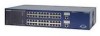
NETGEAR Model FSM726S Managed Stackable Switch. • Twenty-four (FSM726S) or forty-eight (FSM750S) 10/100 Mbps auto sensing Fast Ethernet switching ports • Two Gigabit Ethernet ports that can be used either through the built-in RJ-45 ports for 10/100/1000 Mbps connectivity or through the GBIC modules - Netgear FSM750S | FSM750S Reference Manual - Page 12
or FSM750S Managed Stackable Switch Rubber footpads for tabletop installation Power cord One null-modem cable One stacking cable Rack-mount kit for installing the switch in a 19-inch rack This user's guide Support Information Card Warranty & Owner Registration Card If you ordered additional GBIC - Netgear FSM750S | FSM750S Reference Manual - Page 13
Page 12 of 121 - Netgear FSM750S | FSM750S Reference Manual - Page 14
the hardware features of the NETGEAR Model FSM726S and FSM750S Managed Stackable Switch. Topics include: Front and back panels 10/100 Mbps auto-sensing RJ-45 ports Gigabit Ethernet Ports (RJ-45 and GBIC module bay) LED descriptions Console port Stacking ports Front Panels Figures 2-1 and 2-2 show - Netgear FSM750S | FSM750S Reference Manual - Page 15
Redundant Paths between Network Devices Gigabit Ethernet Ports (RJ-45 and GBIC module bay) Your NETGEAR Model FSM726S and FSM750S Managed Stackable Switch have two Gigabit Ethernet ports that can be used as either a 1000BASE-T port or as a GBIC module bay. The default setting for those ports are for - Netgear FSM750S | FSM750S Reference Manual - Page 16
in a stack of FSM700S switches. Console Port Your NETGEAR Model FSM726S or FSM750S Managed Stackable Switch has a console port on the front panel. This port is labeled Console and is required for initial management configuration of the switch. It also lets you manage the switch using a directly - Netgear FSM750S | FSM750S Reference Manual - Page 17
Page 16 of 121 - Netgear FSM750S | FSM750S Reference Manual - Page 18
include: Desktop switching Stacked Switching Desktop Switching Your NETGEAR Model FSM726S or FSM750S Managed Stackable Switch can be used as desktop switch to build a small network that enables users to have 1000 Mbps access to a file server. With full-duplex enabled, the switch port connected to - Netgear FSM750S | FSM750S Reference Manual - Page 19
Stacked Switching Your NETGEAR Model FSM726S Managed Stackable Switch has two bi-directional stacking ports on the back panel. Using these ports, you can build a full-duplex, switched network for large numbers of users simply by stacking units together. The high-speed stacking ports deliver more - Netgear FSM750S | FSM750S Reference Manual - Page 20
, be sure the mounting surface can safely support the switch stack. Also, be sure there is adequate space around the stack for ventilation and cooling. Step 2: Installing the Switch You can install your NETGEAR Model FSM726S or FSM750S Managed Stackable Switch on a flat surface or in a standard 19 - Netgear FSM750S | FSM750S Reference Manual - Page 21
skip to "Step 5: Checking the Installation." Figure 4-2: Installing a Gigabit Ethernet Module into an FSM726S Step 4: Connecting Switches to the Stack's Backplane Your NETGEAR Model FSM726S or FSM750S Managed Stackable Switch provides two stacking connectors. You can use these connectors to cascade - Netgear FSM750S | FSM750S Reference Manual - Page 22
the problem, refer to Appendix B, Troubleshooting. Note: If you are powering up stacked switches, power up the master unit last. Step 7: Connecting to the Console Port to Manage the Switch (initial configuration) Your NETGEAR Model FSM726S or FSM750S Managed Stackable Switch contains software for - Netgear FSM750S | FSM750S Reference Manual - Page 23
Macintosh, or UNIX workstation that is directly connected to the switch's console port. Thereafter, you can assign an IP address, subnet mask, and gateway address to the switch and manage it through a Web browser, Telnet session, or SNMP management application. For more information about using the - Netgear FSM750S | FSM750S Reference Manual - Page 24
Figure 4-4: System Description 4. The terminal-emulation program should display the System Description page. Hit the 'ESC' key to get to the Main Menu page . Page 23 of 121 - Netgear FSM750S | FSM750S Reference Manual - Page 25
Figure 4-5: Main Menu 5. On the Main Menu page, hit the 'C' key to select the Set Up page Page 24 of 121 - Netgear FSM750S | FSM750S Reference Manual - Page 26
Figure 4-6: Set-Up 6. On the Set Up page, hit the 'B' key to select the IP Configuration page. Page 25 of 121 - Netgear FSM750S | FSM750S Reference Manual - Page 27
in the desired IP Address for this switch, followed by the 'Enter' key. Note: this switch is not DHCP client capable. You must assign a static IP address to the master switch. 8. Now type in the desired Network Mask, followed by the 'Enter' key. 9. Now type in the desired Default Gateway, followed - Netgear FSM750S | FSM750S Reference Manual - Page 28
or 'Enter' to confirm resetting the switch. The switch will now reset, loading the new IP address. At this point you can use your web browser to manage your switch through the network. After you have connected your computer to the switch via one of the network ports, simply launch your web browser - Netgear FSM750S | FSM750S Reference Manual - Page 29
's RJ-45 ports. Your NETGEAR Model FSM726S or FSM750S Managed Stackable Switch contains Auto Uplink™ technology, which allows you to attach devices using either straight-through or crossover cables. Figure 4-9: Connecting Devices to the Switch Connect each device to an RJ-45 network port on the - Netgear FSM750S | FSM750S Reference Manual - Page 30
Software Upgrade Procedure Management Access Overview Your NETGEAR Model FSM726S or FSM750S Managed Stackable Switch gives you the flexibility to access and manage the switch using any or all of the following methods: An administration console Web browser interface External SNMP-based network - Netgear FSM750S | FSM750S Reference Manual - Page 31
one IP address configured on the NETGEAR Model FSM726S/FSM750S Managed Stackable Switch before you can establish access to it with a virtual terminal protocol. Terminal emulation differs from a virtual terminal protocol in that you must connect a terminal or PC directly to the console port. Figure - Netgear FSM750S | FSM750S Reference Manual - Page 32
Restart the system via the Tools>Reset command 11. The new image should over-write the old image in non-volatile memory. Verify it by going to the Software Download screen and checking the Software Release information. Note: IP address, Network Mask, and Default Gateway are not affected by upgrading - Netgear FSM750S | FSM750S Reference Manual - Page 33
Page 32 of 121 - Netgear FSM750S | FSM750S Reference Manual - Page 34
described in chapter 7) to manage the switch. The console, using VT100 terminal emulation, can be accessed from the RS-232 serial port or a telnet connection. The switch offers password protection for this interface. All of the following examples of the Console's User Interface show a screen capture - Netgear FSM750S | FSM750S Reference Manual - Page 35
At the bottom of every screen are some key commands available to the user for that particular screen, as well as some helpful information. The common field Refresh the screen Log off (password enabled) Move to field (Switch Statistics and Port Configuration menus only) Saves current configuration - Netgear FSM750S | FSM750S Reference Manual - Page 36
disabled. If enabled, the default password is '1234'. To enable password protection: o Choose Security from the Main Menu o Toggle Password Protection to Enabled o Enter and verify new password o Save with Ctrl-W Figure 6-2 Initial Welcome screen of User Interface (Password enabled) Page 35 of 121 - Netgear FSM750S | FSM750S Reference Manual - Page 37
items to choose from: o System o Status o Set-Up o Tools o Security o Advanced To logout of the user interface, hit Ctrl-D at anytime during your telnet session. You will be brought back to the login screen (password enabled) or Main Menu (password disabled). Figure 6-3: Main Menu Page 36 of 121 - Netgear FSM750S | FSM750S Reference Manual - Page 38
Main Menu> System This screen displays the following: System uptime System Description System Name- user definable System Contact-user definable System Location-user definable MAC Address Figure 6-4: System Information Page 37 of 121 - Netgear FSM750S | FSM750S Reference Manual - Page 39
are two sub-menus at Status menu, the Switch Statistics and MAC Address Table. Main Menu> Status >Statistics There are two sections in this screen. The Unit number at the top indicates the switch in the stack, and left-side Port-ID field allows you to choose a port to be observed. To get to the - Netgear FSM750S | FSM750S Reference Manual - Page 40
are in the database, the packets intended for those addresses are forwarded directly to those ports. You can filter out addresses in the table by port, VLAN, and/or MAC address by entering a value in those fields, and selecting 'Query'. Figure 6-6: Address Manager: MAC Address Table Page 39 of 121 - Netgear FSM750S | FSM750S Reference Manual - Page 41
bar on the two letters next to the port number. Note: enabling the GBIC connector for a Gigabit Ethernet port disables the built-in 1000BASE-T port. Note: GBIC ports do not support Auto Negotiation. You must manually configure the GBIC port. The default values are 1000 Mbps, full duplex. Page 40 - Netgear FSM750S | FSM750S Reference Manual - Page 42
Figure 6-7: Port Configuration Page 41 of 121 - Netgear FSM750S | FSM750S Reference Manual - Page 43
This menu manages the IP related information of the system. o Enter a site-specific IP address, Gateway Address, and Network Mask (or subnet mask). Consult your network administrator for the information. o Press Ctrl-W to save any changes to NVRAM. Figure 6-8: Set-up Manager: IP Configuration Page - Netgear FSM750S | FSM750S Reference Manual - Page 44
Software Upgrade o Save Configuration o Restore Factory Values o Reset Main Menu> Tools> Software software. Net option: This option allows you to try out a new image before upgrading. It requires a TFTP filename and a server IP address to retrieve the specified image from the given IP address - Netgear FSM750S | FSM750S Reference Manual - Page 45
the configuration to NVRAM. Restore Factory Values Select Restore Factory Values to reset the switch parameters to their original default settings. In order for changes to take effect, you must Reset the switch. Note: network IP settings (i.e. IP address, Gateway Address, Network Mask) will not be - Netgear FSM750S | FSM750S Reference Manual - Page 46
Main Menu> Tools> Reset Reset Switch will restart the switch, the equivalent of turning the power off and on. Reset switch will clear the statistical counters to zero. Figure 6-11: Reset Page 45 of 121 - Netgear FSM750S | FSM750S Reference Manual - Page 47
This screen allows the user to enable or disable the web interface and change the password for both the Console and Web sessions. To use password protection, you must enable Password Protection. If you forget your password, contact NETGEAR technical support at 1-888-NETGEAR (in North America - Netgear FSM750S | FSM750S Reference Manual - Page 48
a way of managing traffic in a network, by treating different types of traffic with different levels of service priority. Higher priority traffic gets faster treatment during times of switch congestion. o VLANs: A Virtual Local Area Network (VLAN) is a means to electronically separate ports on the - Netgear FSM750S | FSM750S Reference Manual - Page 49
Figure 6-13: Port Mirroring Page 48 of 121 - Netgear FSM750S | FSM750S Reference Manual - Page 50
only. For example, a 10/100 port cannot form a Port Trunk with a gigabit port. For 10/100 ports, trunks can only be formed within the same bank. A bank is ports 1 to 8, ports 9 to 16, ports 17 to 24, or port 25 and port 26 (using an FSM726S as an example), on the same switch unit. Up to four trunks - Netgear FSM750S | FSM750S Reference Manual - Page 51
Port Priority allows the user to specify which ports have greater precedence in situations where traffic may be buffered in the switch due to congestion. The ports of a given port, toggle the port's setting from 'normal' to 'high'. The default and normal setting for a port is 'normal'. Figure - Netgear FSM750S | FSM750S Reference Manual - Page 52
Area Network (VLAN) is a means to electronically separate ports on the same switch from a single broadcast domain into separate broadcast domains. By using VLAN, users can group by logical function instead of physical location. This switch supports up to 64 VLANs. This switch supports static, port - Netgear FSM750S | FSM750S Reference Manual - Page 53
with unique ID numbers and names can be added. VLAN ID numbers must be in the range of 1-4094. Add a VLAN 1. Type a unique numeric VLAN ID and hit Enter 2. Type a unique VLAN name and hit Enter Remove a port or an entire VLAN To remove an entire VLAN, just press Ctrl-X anywhere on that line Figure - Netgear FSM750S | FSM750S Reference Manual - Page 54
that the port is not a member of the particular VLAN, and will not get any traffic for that VLAN. VLAN tagging is a standard set by the IEEE to facilitate the spanning of VLANs across multiple switches. (Reference: Appendix C and IEEE Std 802.1Q-1998 Virtual Bridged Local Area Networks) Figure 6-18 - Netgear FSM750S | FSM750S Reference Manual - Page 55
> Advanced Menu> VLANS Setup> VLAN Ports All untagged packets entering the switch will by default be tagged with the ID specified by the port's PVID. This screen allows you to specify the PVID for each port. The number next to each port indicates which PVID is set for each port. Following industry - Netgear FSM750S | FSM750S Reference Manual - Page 56
Main Menu> Advanced Menu> Spanning Tree This switch is compliant with IEEE802.1D Spanning Tree Protocol (STP). STP ensures that only one path at a time is active between any two network nodes. There are maybe more than two physical path between any two nodes for redundant paths; STP ensures only one - Netgear FSM750S | FSM750S Reference Manual - Page 57
> Bridge Settings The following information is presented on this page: o Root Port o Root Port Path Cost o Bridge Hello Time o Bridge Max Age o Bridge Forward Delay o Root Bridge Priority o Root MAC Address o Switch MAC Address Spanning Tree can be enabled or disabled in this screen. Enable: There - Netgear FSM750S | FSM750S Reference Manual - Page 58
. If a client is trying to access a server through the switch running the STP negotiation, it will not be able to connect to it immediately. This can be a problem for some networks. Fastlink mode solves this problem by setting the port directly to forwarding mode, thus allowing any server access - Netgear FSM750S | FSM750S Reference Manual - Page 59
Main Menu> Advanced Menu> MAC Address Manager There are two advanced setup parameter can be configured here. o Static Address o Address Aging Figure 6-23: MAC Page 58 of 121 - Netgear FSM750S | FSM750S Reference Manual - Page 60
Menu> MAC Address Manager> Address Aging The aging time is the amount of time that an entry is kept in the bridge tables prior to being purged (or aged). The range (in parentheses) represents the minimum and the maximum values that the timer can be set. Figure 6-24: MAC: Address Aging Page 59 - Netgear FSM750S | FSM750S Reference Manual - Page 61
Advanced Menu> MAC Address Manager> Static Addresses The Static Addresses Table, allows the administrator to specify Media Access Control (MAC) addresses for specific ports that will not be purged from the bridge table by the aging function. Add an entry o Type the MAC address under the first column - Netgear FSM750S | FSM750S Reference Manual - Page 62
usage by limiting traffic forwarding that is otherwise broadcast to the whole network. Enabling IGMP will allow individual ports to detect IGMP queries, report packets, and manage IP multicast traffic through the switch. IGMP Enable The system will detect IGMP queries, report packets, and - Netgear FSM750S | FSM750S Reference Manual - Page 63
Main Menu> Advanced Menu> SNMP You can manage this switch by SNMP from a network management station. SNMP management features on the switch include: o Simple Network Management Protocol (SNMP) o Support Standard MIBs: • MIB II (RFC1213) • Ethernet Interface MIB (RFC1643) • Bridge MIB (RFC1493) • - Netgear FSM750S | FSM750S Reference Manual - Page 64
Main Menu> Advanced Menu> SNMP> Community Table You can create up to eight different community strings with combinations of GET, SET host table depends on the existence of community strings. The public string has GET privileges by default. Figure 6-28: SNMP Management: Community Table Page 63 of 121 - Netgear FSM750S | FSM750S Reference Manual - Page 65
. If Host Authorization is enabled, the host must be added to this table, through the Console port connection in order for an end station to be access the switch via SNMP. Add host o Enter the host name, IP address, and the community string. Press Enter after each entry to move to the next field - Netgear FSM750S | FSM750S Reference Manual - Page 66
> Advanced Menu> SNMP> Trap Settings Authentication Traps When on, the system will generate an SNMP trap upon a host authorization failure. This failure occurs when a host tries to gain access to the system but the host's IP is not in the SNMP host table. Figure 6-30: SNMP Management: Trap Settings - Netgear FSM750S | FSM750S Reference Manual - Page 67
Page 66 of 121 - Netgear FSM750S | FSM750S Reference Manual - Page 68
by entering the switch's IP address into the address bar. In this way, you can use your Web browser to manage the switch from a central location, just as if you were directly connected to the switch's console port. Figure 7-1 shows this management method. Figure 7-1: Web Management Method Web - Netgear FSM750S | FSM750S Reference Manual - Page 69
data Remove: Removes selected entries from table and refreshes screen data Reset: Reset system, the action is equivalent to power off /on. Restore: Restore the system factory default value, except password and IP. Query: System will retrieve the useful information in database. Page 68 - Netgear FSM750S | FSM750S Reference Manual - Page 70
welcome page, which displays system information, such as: o System Description o System Name o System Contact o System Location o MAC Address o IP Address o Subnet Mask o Default Gateway o Software Version These parameters are not editable from this screen. They can be modified in the Set Up> System - Netgear FSM750S | FSM750S Reference Manual - Page 71
Switch Statistics o Port Statistics o Port Settings o MAC Address Table o Error Chart Status > Switch Statistics The Switch Statistics Chart allows you to compare one type of statistic across all the ports. Switch Ethernet Undersize Packet Rate: Less than 64byte length packet per second. Ethernet - Netgear FSM750S | FSM750S Reference Manual - Page 72
Figure 7-4: Statistics: Switch Statistics Page 71 of 121 - Netgear FSM750S | FSM750S Reference Manual - Page 73
packet. Outbound Discards: Transmitted and is being discarded packet Outbound Errors: Transmitted and is an Error packet. Ethernet Undersize Packets: Less than 64byte length packet Ethernet Oversize Packets: more than 1518 byte length packet. Figure 7-5: Statistics: Port Statiscis Page 72 of 121 - Netgear FSM750S | FSM750S Reference Manual - Page 74
port settings. To configure the ports, go to the 'Port Configuration' under the 'Set-up' sub menu. o Port Number: The port number on the switch o Port Name: The name of the port. This is a user Control support is set for automatic (Auto) or off (Disabled) o Priority Indicates if the port is - Netgear FSM750S | FSM750S Reference Manual - Page 75
currently in the address database. When addresses are in the database, the packets intended for those addresses are forwarded directly to those ports. You can filter the displayed addresses by port, VLAN, and/or MAC address by checking those fields. Figure 7-7: Status Manager: MAC Address Table Page - Netgear FSM750S | FSM750S Reference Manual - Page 76
o Statistics The type of system errors to be monitored o Refresh Rate The time interval between automatic refreshes (5,10,15, 30 seconds) o Port Selection The port for data to be monitored When all of the variables are set, click Draw. Figure 7-8: Statistics: Error Statistics Page 75 of 121 - Netgear FSM750S | FSM750S Reference Manual - Page 77
Set-up There are four kinds of configuration in the Setup page: o System Configuration o IP Configuration o Port Configuration o Gigabit Port Configuration (GBIC) Set-up> System Configuration This page will allow access to the system information parameters. o Enter System Name, System Contact, - Netgear FSM750S | FSM750S Reference Manual - Page 78
can manage this switch over the network using its IP address, as set in this menu. There are three tunable parameters to be set by the system administrator. o Enter site-specific IP address, Gateway address and Net mask o Click Apply to change the IP settings o Save Configuration to NVRAM and reset - Netgear FSM750S | FSM750S Reference Manual - Page 79
the status per port at 'Port Configuration' menu. o Port Number: The port number on the switch o Port Name: The name of the port. This is a user-defined label. o Full). o Flow Control: Indicates whether Flow Control support is set for automatic (Auto) or off (Disabled) Figure 7-11: Setup - Netgear FSM750S | FSM750S Reference Manual - Page 80
to choose the port type of the gigabit ports. The default is copper (RJ-45). If the user chooses to use a GBIC, the setting on this page must be appropriately set. Note: enabling the GBIC connector for a Gigabit Ethernet port disables the built-in 1000BASE-T port. Figure 7-12: Setup: GBIC Page 79 of - Netgear FSM750S | FSM750S Reference Manual - Page 81
boot from the boot image last saved in non-volatile memory in the switch. For booting from the network, supply the TFTP server IP address and boot image file name, then select 'Apply'. Net option This option allows the user to try out a new image before upgrading. It requires a TFTP filename and - Netgear FSM750S | FSM750S Reference Manual - Page 82
are not saved to NVRAM, then they will be lost during the next switch reset or reboot. Restore the factory configuration by selecting 'Restore'. Note: network IP settings (i.e. IP address, Gateway Address, Network Mask) will not be affected by the Restore command. Figure 7-14: Save Configuration - Netgear FSM750S | FSM750S Reference Manual - Page 83
Tools> Device Reset In this screen the user can reset (power cycle) the switch. This is primarily used to upgrade the firmware or restore defaults. Reset the switch by selecting 'Reset' Figure 7-15: Device Reset Page 82 of 121 - Netgear FSM750S | FSM750S Reference Manual - Page 84
new administrator password in the New password field o Type the same password in the Verify field o Click Apply to activate the new password Note: If you have enabled password protection without setting your own password, the default password is '1234'. Figure 7-16: System Manager: Password Admin - Netgear FSM750S | FSM750S Reference Manual - Page 85
a way of managing traffic in a network, by treating different types of traffic with different levels of service priority. Higher priority traffic gets faster treatment during times of switch congestion. o VLANs: A Virtual Local Area Network (VLAN) is a means to electronically separate ports on the - Netgear FSM750S | FSM750S Reference Manual - Page 86
feature to help in the debugging of a network. This web interface page allows the enabling or disabling of port mirroring and the setting of source and monitor ports. The monitor port will show a copy of every packet that arrives or leaves the source port. Figure 7-18: Port Mirroring Page 85 of 121 - Netgear FSM750S | FSM750S Reference Manual - Page 87
, trunks can only be formed within the same bank. A bank is a group of 8 10/100 ports or 2 gigabit ports, for example, ports 1 to 8, ports 9 to 16, ports 17 to 24, or port 25 and port 26, on the same switch unit. Up to four trunks can be enabled at the same time within a stack. To set up a trunk - Netgear FSM750S | FSM750S Reference Manual - Page 88
be removed from the packet before it leaves the switch if that exiting port is designated a VLAN untagged port. To raise the priority of a given port, switch the port's setting from 'normal' to 'high'. The default and normal setting for a port is 'normal'. Figure 7-20: Traffic Priortization Settings - Netgear FSM750S | FSM750S Reference Manual - Page 89
Network (VLAN) is a means to electronically separate ports on the same switch from a single broadcast domain into separate broadcast domains. By using VLAN, users can group by logical function instead of physical location. There are 64VLAN supported on this switch. This switch supports static, port - Netgear FSM750S | FSM750S Reference Manual - Page 90
Figure 7-21: VLANS: VLAN's and Primary VLAN Advanced> VLAN> VLAN Port All untagged packets entering the switch will by default be tagged as specified by the port's Primary VLAN Identification (PVID). This screen allows you to specify the PVID for each port. Page 89 of 121 - Netgear FSM750S | FSM750S Reference Manual - Page 91
Figure 7-22: VLAN: VLAN Port Settings Page 90 of 121 - Netgear FSM750S | FSM750S Reference Manual - Page 92
that only one path at a time is active between any two network nodes. There are maybe more than two physical path between any two the others are blocked. STP will prevent an inadvertent loop in a network, which can disable your network due to a "Broadcast storm", the result of a broadcast message - Netgear FSM750S | FSM750S Reference Manual - Page 93
Settings The following information is presented on the this page: o Root Port o Root Port Path Cost o Bridge Hello Time o Bridge Max Age o Bridge Forward Delay o Root Bridge Priority o Root MAC Address o Switch MAC Address Spanning Tree can be enabled or disabled in this screen. Enable: There - Netgear FSM750S | FSM750S Reference Manual - Page 94
. If a client is trying to access a server through the switch running the STP negotiation, it will not be able to connect to it immediately. This can be a problem for some networks. Fastlink mode solves this problem by setting the port directly to forwarding mode, thus allowing any server access - Netgear FSM750S | FSM750S Reference Manual - Page 95
of time an entry is held in the forwarding tables while no activity occurs from that address. Entries should be removed to update the table for MAC addresses that have moved or are turned off. The default value is set to 300 seconds (5 minutes). o The administrator may change this value to any value - Netgear FSM750S | FSM750S Reference Manual - Page 96
Advanced> MAC> Static Addresses Any system, whose MAC address and the port number are listed in this screen, will not be purged from the system's forwarding table by the aging process. Add a new entry o Enter the MAC address and port in the appropriate boxes o Click Add Remove an exist entry o - Netgear FSM750S | FSM750S Reference Manual - Page 97
usage by limiting traffic forwarding that is otherwise broadcast to the whole network. Enabling IGMP will allow individual ports to detect IGMP queries, report packets, and manage IP multicast traffic through the switch. IGMP Enable The system will detect IGMP queries, report packets, and - Netgear FSM750S | FSM750S Reference Manual - Page 98
Figure 7-28: Multimedia Support > Static Multicast Groups Page 97 of 121 - Netgear FSM750S | FSM750S Reference Manual - Page 99
SNMP Users can manage this switch by SNMP from a network management station. SNMP management features on the switch include: o Simple Network Management Protocol (SNMP) o Support Standard MIBs: • MIB II (RFC1213) • Ethernet by default. Figure 7-29: SNMP Management: Community Table Page 98 of 121 - Netgear FSM750S | FSM750S Reference Manual - Page 100
their IP address to the appropriate community string. Host Authorization can be Enabled or Disabled. If Host Authorization is enabled, the host must be added to this table, through the Console port connection in order for an end station to be access the switch via SNMP. Figure 7-30: SNMP Management - Netgear FSM750S | FSM750S Reference Manual - Page 101
failure. This failure occurs when a host tries to gain access to the system but the host's IP is not in the SNMP host table. Authentication traps o Enable The system will generate a SNMP trap upon a host authorization failure o Disable The authentication traps will not be generated All hosts in - Netgear FSM750S | FSM750S Reference Manual - Page 102
can indicate a problem with a device, particularly if it is not accompanied by a general increase in traffic. A computer, printer, or server that is connected to a network. A LAN specification developed jointly by Xerox, Intel and Digital Equipment Corporation. Ethernet networks transmit packets at - Netgear FSM750S | FSM750S Reference Manual - Page 103
IEEE IETF IGMP IP IP address IP multicast LAN Load balancing Loop MAC MAC address Multicast Port monitoring Port speed Port trunking Protocol Quality of Service Segment SNMP Spanning Tree Spanning Tree Protocol (STP) Switch TCP/IP Institute of Electrical and Electronics Engineers. This American - Netgear FSM750S | FSM750S Reference Manual - Page 104
software upgrades) from a remote device using the local management capabilities of the Switch. Giving time-critical data traffic a higher quality of service over other, non-critical data traffic. A packet sent to a single end station on a network. Virtual LAN. A logical association that allows users - Netgear FSM750S | FSM750S Reference Manual - Page 105
Page 104 of 121 - Netgear FSM750S | FSM750S Reference Manual - Page 106
about troubleshooting the NETGEAR Model FSM726S or FSM750S Managed Stackable Switch. Topics include: o Troubleshooting chart o Additional troubleshooting suggestions Troubleshooting Chart Table B-1 lists symptoms, causes, and solutions of possible problems. Table B-1. Troubleshooting Chart - Netgear FSM750S | FSM750S Reference Manual - Page 107
Page 106 of 121 - Netgear FSM750S | FSM750S Reference Manual - Page 108
FSM750S Managed Stackable Switch Packets received by the switch will be treated in the following way: o When an untagged packet enters a port, it will be automatically tagged with the port's default VLAN ID tag number. Each port has a default VLAN ID setting that is user configurable (the default - Netgear FSM750S | FSM750S Reference Manual - Page 109
the basics of setting up a VLAN. 1. In the VLAN Administration page, add a new VLAN to the list, shown below as "First" with a VLAN ID value of 2. 2. In the VLAN Membership page, use the space bar to modify the matrix until the desired ports are all members of the selected VLAN as either tagged or - Netgear FSM750S | FSM750S Reference Manual - Page 110
Page 109 of 121 - Netgear FSM750S | FSM750S Reference Manual - Page 111
3. To allow untagged packets to participate in the 'First' VLAN, make sure to change the Port VLAN IDs for the relevant ports. Access the PVID Settings page then use the space bar to add an 'X' indicating which Port VLAN ID is assigned to which port. Page 110 of 121 - Netgear FSM750S | FSM750S Reference Manual - Page 112
VLAN and non-VLAN traffic. 1) Setup the following VLANs: 2) Configure the VLAN membership. Each image below shows a different VLAN to be setup. Be sure to set all of them as follows. Note: this example uses a single switch, but the same principles apply to a VLAN that had ports on several switches - Netgear FSM750S | FSM750S Reference Manual - Page 113
Page 112 of 121 - Netgear FSM750S | FSM750S Reference Manual - Page 114
Page 113 of 121 - Netgear FSM750S | FSM750S Reference Manual - Page 115
: 10 Port 11: 10 Port 12: 10 Port 13: 10 Port 14: 15 Port 15: 1 Port 16: 1 The following scenarios will produce results as described below: 1) If an untagged packet enters Port 4, the switch will tag it with a VLAN tag value of 1. Since Port 4 does not have membership with VLAN ID 1 (default), the - Netgear FSM750S | FSM750S Reference Manual - Page 116
provides technical specifications for the NETGEAR Model and FSM750S Managed Stackable Switch. Network Protocol and Standards Compatibility IEEE 802.3 10BASE-T IEEE 802.3u 100BASE-TX IEEE 802.3z 1000BASE-SX IEEE 802.3ab 1000BASE-T IEEE 802.3x flow control Management IEEE 802.1Q Static VLAN (Up to - Netgear FSM750S | FSM750S Reference Manual - Page 117
-1 EN 55024 Safety CE mark, commercial CSA certified (CSA 22.2 #950) TUV licensed (EN 60 950) UL listed (UL 1950)/cUL IEC950/EN60950 Modules AGM721F GBIC SX module for 1000BASE-SX connection with SC connectors for 50um or 62.5um multi-mode fiber cable Page 116 of 121 - Netgear FSM750S | FSM750S Reference Manual - Page 118
NETGEAR Model FSM726S or FSM750S Managed Stackable Switch. RJ-45 Plug and RJ-45 Connector In a Fast Ethernet network to connect stations, hubs, and switches through UTP cable; it supports 10 Mbps, 100 Mbps, or Pin Normal Assignment on Ports 1 to 8 Uplink Assignment on Port 8 1 Input Receive - Netgear FSM750S | FSM750S Reference Manual - Page 119
Page 118 of 121 - Netgear FSM750S | FSM750S Reference Manual - Page 120
GUIDELINES This appendix provides specifications for cables used with the NETGEAR Model FSM726S or FSM750S Managed Stackable Switch. Fast Ethernet Cable Guidelines Fast Ethernet uses UTP cable, as specified in the IEEE 802.3u standard for 100BASE-TX.The specification requires Category 5 UTP cable - Netgear FSM750S | FSM750S Reference Manual - Page 121
you are using patch panels, make sure that they meet the 100BASE-TX requirements. NETGEAR recommends Category 5 UTP cable for all patch cables and work area cables to ensure results in excessive collisions, causing the attached port to be partitioned or disconnected from the network. Page 120 of 121 - Netgear FSM750S | FSM750S Reference Manual - Page 122
implemented. The following sections are designed to act as a guide to correct cabling for 1000BASE-T. Cabling The 1000BASE-T product :1995 Category 5 specifications. Length The maximum distance limitation between two pieces of equipment is 100 m, as per the original Ethernet specification. The end-to - Netgear FSM750S | FSM750S Reference Manual - Page 123
-
 1
1 -
 2
2 -
 3
3 -
 4
4 -
 5
5 -
 6
6 -
 7
7 -
8
-
9
-
10
-
11
-
12
-
13
-
14
-
15
-
16
-
17
-
18
-
19
-
20
-
21
-
22
-
23
-
24
-
25
-
26
-
27
-
28
-
29
-
30
-
31
-
32
-
33
-
34
-
35
-
36
-
37
-
38
-
39
-
40
-
41
-
42
-
43
-
44
-
45
-
46
-
47
-
48
-
49
-
50
-
51
-
52
-
53
-
54
-
55
-
56
-
57
-
58
-
59
-
60
-
61
-
62
-
63
-
64
-
65
-
66
-
67
-
68
-
69
-
70
-
71
-
72
-
73
-
74
-
75
-
76
-
77
-
78
-
79
-
80
-
81
-
82
-
83
-
84
-
85
-
86
-
87
-
88
-
89
-
90
-
91
-
92
-
93
-
94
-
95
-
96
-
97
-
98
-
99
-
100
-
101
-
102
-
103
-
104
-
105
-
106
-
107
-
108
-
109
-
110
-
111
-
112
-
113
-
114
-
115
-
116
-
117
-
118
-
119
-
120
-
121
-
122
-
123
 |
 |
