Netgear FWG114P FWG114Pv2 Reference Manual - Page 275
Type the finishing LAN IP Address of Gateway
 |
UPC - 606449029819
View all Netgear FWG114P manuals
Add to My Manuals
Save this manual to your list of manuals |
Page 275 highlights
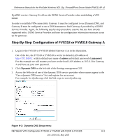
Reference Manual for the ProSafe Wireless 802.11g Firewall/Print Server Model FWG114P v2 Figure H-4: NETGEAR FVS318 VPN Settings (part 1) - Main Mode - In the Connection Name box, enter in a unique name for the VPN tunnel to be configured between the NETGEAR devices. For this example we have used toFVS328. - Enter a Local IPSec Identifier name for the NETGEAR FVS318 Gateway A. This name must be entered in the other endpoint as Remote IPSec Identifier. In this example we used netgear.dyndns.org (the FQDN) as the local identifier. - Enter a Remote IPSec Identifier name for the remote NETGEAR FVS328 Gateway B. This name must be entered in the other endpoint as Local IPSec Identifier. In this example we used 22.23.24.25 as the remote identifier. - Choose a subnet from local address from the "Tunnel can be accessed" from pull-down menu. - Type the starting LAN IP Address of Gateway A (10.5.6.1 in our example) in the Local IP Local LAN start IP Address field. - Type the finishing LAN IP Address of Gateway A (0.0.0.0 in our example) in the Local IP Local LAN finish IP Address field. - Type the LAN Subnet Mask of Gateway A (255.255.255.0 in our example) in the Local LAN IP Subnetmask field. - Choose a subnet from local address from the "Tunnel can access" pull-down menu. - Type the starting LAN IP Address of Gateway B (172.23.9.1 in our example) in the Local IP Remote LAN Start IP Address field. NETGEAR VPN Configuration FVS318 or FVM318 with FQDN to FVS328 H-5 201-10301-02, May 2005
-
 1
1 -
2
-
3
-
4
-
5
-
6
-
7
-
8
-
9
-
10
-
11
-
12
-
13
-
14
-
15
-
16
-
17
-
18
-
19
-
20
-
21
-
22
-
23
-
24
-
25
-
26
-
27
-
28
-
29
-
30
-
31
-
32
-
33
-
34
-
35
-
36
-
37
-
38
-
39
-
40
-
41
-
42
-
43
-
44
-
45
-
46
-
47
-
48
-
49
-
50
-
51
-
52
-
53
-
54
-
55
-
56
-
57
-
58
-
59
-
60
-
61
-
62
-
63
-
64
-
65
-
66
-
67
-
68
-
69
-
70
-
71
-
72
-
73
-
74
-
75
-
76
-
77
-
78
-
79
-
80
-
81
-
82
-
83
-
84
-
85
-
86
-
87
-
88
-
89
-
90
-
91
-
92
-
93
-
94
-
95
-
96
-
97
-
98
-
99
-
100
-
101
-
102
-
103
-
104
-
105
-
106
-
107
-
108
-
109
-
110
-
111
-
112
-
113
-
114
-
115
-
116
-
117
-
118
-
119
-
120
-
121
-
122
-
123
-
124
-
125
-
126
-
127
-
128
-
129
-
130
-
131
-
132
-
133
-
134
-
135
-
136
-
137
-
138
-
139
-
140
-
141
-
142
-
143
-
144
-
145
-
146
-
147
-
148
-
149
-
150
-
151
-
152
-
153
-
154
-
155
-
156
-
157
-
158
-
159
-
160
-
161
-
162
-
163
-
164
-
165
-
166
-
167
-
168
-
169
-
170
-
171
-
172
-
173
-
174
-
175
-
176
-
177
-
178
-
179
-
180
-
181
-
182
-
183
-
184
-
185
-
186
-
187
-
188
-
189
-
190
-
191
-
192
-
193
-
194
-
195
-
196
-
197
-
198
-
199
-
200
-
201
-
202
-
203
-
204
-
205
-
206
-
207
-
208
-
209
-
210
-
211
-
212
-
213
-
214
-
215
-
216
-
217
-
218
-
219
-
220
-
221
-
222
-
223
-
224
-
225
-
226
-
227
-
228
-
229
-
230
-
231
-
232
-
233
-
234
-
235
-
236
-
237
-
238
-
239
-
240
-
241
-
242
-
243
-
244
-
245
-
246
-
247
-
248
-
249
-
250
-
251
-
252
-
253
-
254
-
255
-
256
-
257
-
258
-
259
-
260
-
261
-
262
-
263
-
264
-
265
-
266
-
267
-
268
-
269
-
 270
270 -
 271
271 -
 272
272 -
 273
273 -
 274
274 -
 275
275 -
 276
276 -
 277
277 -
 278
278 -
 279
279 -
 280
280 -
281
-
282
-
283
-
284
-
285
-
286
-
287
-
288
-
289
-
290
-
291
-
292
-
293
-
294
-
295
-
296
 |
 |
