Netgear GS108T GS108T Hardware manual - Page 19
Reset Button, Table 2-1., Front Panel LEDs continued
 |
UPC - 606449051377
View all Netgear GS108T manuals
Add to My Manuals
Save this manual to your list of manuals |
Page 19 highlights
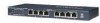
GS108T Smart Switch Hardware Installation Guide Table 2-1. Front Panel LEDs (continued) 10Mbps Link / ACT LED (Right LED) n/a Green Green 1000Mbps Link / ACT LED (Both LEDs) n/a Green Green Off No 10Mbps link is established on the port On - Solid A valid 10Mbps link is established on the port On - Blinking Packets transmission or reception is occurring on the port, linked at 10Mbps mode Off No 1000Mbps link is established on the port On - Solid A valid 1000Mbps link is established on the port On - Blinking Packets transmission or reception is occurring on the port, linked at 1000Mbps mode Reset Button The Reset button of the GS108T triggers a hardware reset of the switch. Figure 2-3 shows its location on the front panel. This action is equivalent to switching the unit power off and back on. The last saved configuration is loaded into the switch as it resets. To operate the reset button, insert a device such as a paper clip into the opening to press the recessed button. The front-panel LEDs should extinguish and light again as the switch performs its Power On Self Test (POST). Physical Description 2-3 v1.0, March 2007
-
 1
1 -
2
-
3
-
4
-
5
-
6
-
7
-
8
-
9
-
10
-
11
-
12
-
13
-
 14
14 -
 15
15 -
 16
16 -
 17
17 -
 18
18 -
 19
19 -
 20
20 -
 21
21 -
 22
22 -
 23
23 -
 24
24 -
25
-
26
-
27
-
28
-
29
-
30
-
31
-
32
-
33
-
34
-
35
-
36
-
37
-
38
 |
 |
