Netgear GS516UP Installation Guide - Page 2
Specifications
 |
View all Netgear GS516UP manuals
Add to My Manuals
Save this manual to your list of manuals |
Page 2 highlights
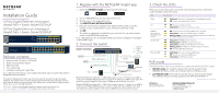
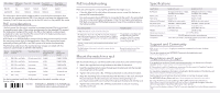
PoE++ Mode DIP Switch Ports 1-4 Position 802.3bt Up Default pre-802.3bt Down Optional Ports 5-8 Default Optional Ports 9-12 Ports 13-16 (GS524UP Only) (GS524UP Only) Default Default Optional Optional For information about which mode to select, consult the documentation that came with the powered device (PD). If you are not sure, keep the default mode. However, if the PD does not power up, set the DIP switch to the pre-802.3bt mode. PoE considerations The PoE power that the switch supplies to powered devices (PDs) is prioritized in ascending port order. If the power requirements for the attached PDs exceed the total power budget of the switch, the PD on the highest-numbered port is disabled to make sure that the PDs connected to the higher-priority, lowernumbered ports are supported first. A PD listed as an 802.3bt PoE++ powered device does not necessarily require the maximum power limit of the specification. Many PDs require less power, potentially allowing all PoE++ and PoE+ ports to be active simultaneously. The following table shows the standard power ranges calculated with the maximum cable length of 328 feet (100 meters). Device Compatible PoE Class standard Class Description Maximum Power Supplied by the Switch Power Delivered to the PD 0 PoE, PoE+, and PoE++ Default power (full) 0.44W 0.44W-12.95W 1 PoE, PoE+, and PoE++ Very low power 4.0W 0.44W-3.84W 2 PoE, PoE+, and PoE++ Low power 7.0W 3.84W-6.49W 3 PoE, PoE+, and PoE++ Mid power 15.4W 6.49W-12.95W 4 PoE+ and PoE++ High power 30.0W 12.95W-25.5W 5-6 PoE++ only Ultra power 45.0W 25.5W-51W If a device receives insufficient PoE power from the switch, consider using a shorter cable. May 2020 © NETGEAR, Inc., NETGEAR and the NETGEAR Logo are trademarks of NETGEAR, Inc. Any non‑NETGEAR trademarks are used for reference purposes only. PoE troubleshooting Here are some tips for correcting PoE problems that might occur: • If the PoE Max LED is solid yellow, disconnect one or more PoE devices to prevent PoE oversubscription. • For each powered device (PD) that is connected to the switch, the associated PoE LED on the switch lights solid green. If the PoE LED lights solid yellow, a PoE fault occurred and PoE halted because of one of the conditions listed in the following table. PoE Fault Condition Possible Solution A PoE-related short circuit occurred on the port. The PoE power demand of the PD exceeded the maximum level that the switch permits. The maximum level is 15.4W for a PoE connection, 30W for a PoE+ connection, and 60W for a PoE++ connection. The PoE current on the port exceeded the classification limit of the PD. The problem is most likely with the attached PD. Check the condition of the PD, or restart the PD by disconnecting and reconnecting the PD. The PoE voltage of the port is outside the range that the switch permits Restart the switch to see if the condition resolves itself. Mount the switch in a rack We recommend that you use the brackets and screws that came with the switch. 1. Attach the supplied mounting brackets to the side of the switch. 2. Insert the supplied small screws through each bracket and into the bracket mounting holes in the switch. 3. Tighten the screws with a No. 1 Phillips screwdriver to secure each bracket. 4. Align the mounting holes in the brackets with the holes in the rack, and insert the provided pan-head screws (you can choose among two types of pan-head screws) with nylon washers through each bracket and into the rack. 5. Tighten the screws with a No. 2 Phillips screwdriver to secure mounting brackets to the rack. Specifications Specification RJ-45 ports PoE++ ports PoE+ ports Maximum PoE budget AC power input Dimensions (W x D x H) Weight Operating temperature Operating humidity Compliance Model GS516UP Model GS524UP 16 Gigabit Ethernet for 1 Gbps, 24 Gigabit Ethernet for 1 Gbps, 100 Mbps, and 10 Mbps. 100 Mbps, and 10 Mbps. 8 (ports 1-8) 16 (ports 1-16) 8 (ports 9-16) 8 (ports 17-24) 380W for the entire switch 480W for the entire switch 100-240V ~ 50/60 Hz, 8-4A 100-240V ~ 50/60 Hz, 8-4A 13.0 x 8.2 x 1.7 in. (330 x 207 x 43 mm) 15.4 x 8.7 x 1.7 in. (390 x 220 x 43 mm) 5.73 lb (2.6 kg) 6.83 lb (3.1 kg) 32-122°F (0-50°C) 10%-90% relative humidity, noncondensing FCC class A, UL 62368-1, CB, CE LVD, CE class A, VCCI class A, RCM class A, KC, BSMI Support and Community Visit netgear.com/support to get your questions answered and access the latest downloads. You can also check out our NETGEAR Community for helpful advice at community.netgear.com. Regulatory and Legal Si ce produit est vendu au Canada, vous pouvez accéder à ce document en français canadien à https://www.netgear.com/support/download/. (If this product is sold in Canada, you can access this document in Canadian French at https://www.netgear.com/support/download/.) For regulatory compliance information including the EU Declaration of Conformity, visit https://www.netgear.com/about/regulatory/. See the regulatory compliance document before connecting the power supply. For NETGEAR's Privacy Policy, visit https://www.netgear.com/about/privacy-policy. By using this device, you are agreeing to NETGEAR's Terms and Conditions at https://www.netgear.com/about/terms-and-conditions. If you do not agree, return the device to your place of purchase within your return period. Do not use this device outdoors. The PoE source is intended for intra building connection only.
-
 1
1 -
 2
2
 |
 |
