Netgear GS716Tv2 GS716Tv2/GS724Tv3 Hardware manual
Netgear GS716Tv2 - ProSafe Gigabit Managed Switch Manual
 |
View all Netgear GS716Tv2 manuals
Add to My Manuals
Save this manual to your list of manuals |
Netgear GS716Tv2 manual content summary:
- Netgear GS716Tv2 | GS716Tv2/GS724Tv3 Hardware manual - Page 1
GS716T/GS724T Hardware Installation Guide NETGEAR, Inc. 350 East Plumeria Drive San Jose, California 95134 USA 202-10510-01 June 2009 v1.0 - Netgear GS716Tv2 | GS716Tv2/GS724Tv3 Hardware manual - Page 2
NETGEAR does not assume any liability that may occur due to the use or application of the product(s) or circuit layout(s) described herein. Certificate of the Manufacturer/Importer It is hereby certified that the Smart Switch the notes in the operating instructions. The Federal Office for - Netgear GS716Tv2 | GS716Tv2/GS724Tv3 Hardware manual - Page 3
GS724T Front and Back Panel Configuration 2-6 LED Designations ...2-7 Port LEDs ...2-7 System LEDs ...2-8 Device Hardware Interfaces 2-8 RJ-45 Ports ...2-8 SFP GBIC Module ...2-9 Factory Defaults Button 2-9 Chapter 3 Applications Desktop Switching ...3-11 Chapter 4 Installation Step 1: Preparing - Netgear GS716Tv2 | GS716Tv2/GS724Tv3 Hardware manual - Page 4
using a Web Browser or the PC Utility 4-18 Appendix A Troubleshooting Troubleshooting Chart A-19 Additional Troubleshooting Suggestions A-20 Network Adapter Cards A-20 Configuration ...A-20 Switch Integrity ...A-20 Auto-Negotiation A-21 Appendix B Technical Specifications Index iv v1.0, June - Netgear GS716Tv2 | GS716Tv2/GS724Tv3 Hardware manual - Page 5
Manual The NETGEAR® ProSafeTM GS716T/GS724T Hardware Installation Guide describes how to install, configure and troubleshoot the Smart Switch. The information in this manual extensions User input, IP addresses, GUI screen text Command prompt, CLI text, code URL links • Formats. This manual uses - Netgear GS716Tv2 | GS716Tv2/GS724Tv3 Hardware manual - Page 6
injury or death. • Scope. This manual is written for the Smart Switch according to these specifications: Product Version Manual Publication Date Smart Switch June 2009 Note: Product updates are available on the NETGEAR, Inc. website at http://kbserver.netgear.com/main.asp. Revision History - Netgear GS716Tv2 | GS716Tv2/GS724Tv3 Hardware manual - Page 7
. With a Webbased Graphical User Interface (GUI), the switch's many capabilities can be viewed and used in a simple and intuitive manner. The switch's management features include configuration for port and switch information, VLAN for traffic control, port trunking for increased bandwidth, and - Netgear GS716Tv2 | GS716Tv2/GS724Tv3 Hardware manual - Page 8
with fiber port taking priority if both are connected. The following SFP types are supported: • 1000BASE-SX • 1000BASE-LX • 100BASE-FX • The devices support full NETGEAR Smart Switch functionality. • The devices provide full compatibility with IEEE standards: • IEEE 802.3i, (10BASE-T) • IEEE 802.3u - Netgear GS716Tv2 | GS716Tv2/GS724Tv3 Hardware manual - Page 9
loss/frame drops. • Half-duplex back-pressure control. • Per port LEDs, System LEDs. • Standard 1U high, rack-mountable 17-inch chassis. • Fan speed control supported. Package Contents Figure 1-1 shows the package contents of the NETGEAR GS716T and GS724T Series Smart Switch. Reset PWR ® ProSafe - Netgear GS716Tv2 | GS716Tv2/GS724Tv3 Hardware manual - Page 10
contains the following: • NETGEAR Smart Switch • Rubber footpads for tabletop installation • Power cord • Rack-mount kit for installing the switch in a 19-inch rack • Installation guide • Smart Switch Resource CD with Smart Wizard Discovery and User's manual • Warranty/Support Information Card If - Netgear GS716Tv2 | GS716Tv2/GS724Tv3 Hardware manual - Page 11
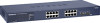
10/100/1000 Mbps auto sensing Gigabit Ethernet switching ports. • Two SFP slots for SFP modules supporting 1000 (1000BASE-SX/LX)/100 Mbps SFP. • Reset button to restart the device. • Recessed default reset button to restore the device back to the factory defaults. • Port LEDs 2-5 v1.0, June 2009 - Netgear GS716Tv2 | GS716Tv2/GS724Tv3 Hardware manual - Page 12
auto-sensing Gigabit Ethernet switching ports. • Two slots for SFP slots for SFP modules supporting 1000 (1000BASE-SX/LX)/100 Mbps SFP. • Reset button to restart the device. • Recessed default reset button to restore the device back to the factory defaults. 2-6 Physical Description v1.0, June - Netgear GS716Tv2 | GS716Tv2/GS724Tv3 Hardware manual - Page 13
GS716T/GS724T Hardware Installation Guide • System LEDs Figure 2-4 illustrates the NETGEAR GS724T Smart Switch back panel: Figure 2-4 100-240V ~ 50-60Hz RS-232 Power Connector The back panel contains the following: • A 100-240VAC/50-60 Hz universal input, which - Netgear GS716Tv2 | GS716Tv2/GS724Tv3 Hardware manual - Page 14
GS716T/GS724T Hardware Installation Guide Table 2-1. Port LEDs (continued) Port 2 SFP Ports - 1 45 port, the switch automatically ascertains the maximum speed (10, 100, or 1000 Mbps) and duplex mode (halfduplex or full-duplex) of the attached device. All ports support only unshielded twisted-pair - Netgear GS716Tv2 | GS716Tv2/GS724Tv3 Hardware manual - Page 15
module. Factory Defaults Button The Smart Switch has a Factory Default button so that you can remove the current configuration and return the device to its factory settings. When you enable the Factory Default button, all settings, including the password, VLAN settings and port configurations will - Netgear GS716Tv2 | GS716Tv2/GS724Tv3 Hardware manual - Page 16
to provide flexibility in configuring your network connections. It can be used as a stand-alone device or with 10 Mbps, 100 Mbps, and 1000 Mbps hubs and switches. Desktop Switching The NETGEAR Smart Switch can be used as a desktop switch to build a small network that enables users to have 1000 Mbps - Netgear GS716Tv2 | GS716Tv2/GS724Tv3 Hardware manual - Page 17
chapter describes the installation procedures for your NETGEAR Smart Switch. Switch installation involves the following steps: Step 1: Preparing the Site Step 2: Installing the Switch Step 3: Checking the Installation Step 4: Connecting Devices to the Switch Step 5: Installing an SFP GBIC Module - Netgear GS716Tv2 | GS716Tv2/GS724Tv3 Hardware manual - Page 18
of electromagnetic noise, such as a photocopy machine. Step 2: Installing the Switch The NETGEAR Smart Switch can be installed on a flat surface or in a standard 19-inch rack. Installing the Switch on a Flat Surface The switch ships with four self-adhesive rubber footpads. Stick one rubber footpad - Netgear GS716Tv2 | GS716Tv2/GS724Tv3 Hardware manual - Page 19
GS716T/GS724T Hardware Installation Guide 5. Tighten the screws with a #2 Phillips screwdriver to secure the switch in the rack. Figure 4-1 Step 3: Checking the Installation Before applying power perform the following: • Inspect the equipment thoroughly. • Verify that all cables are installed - Netgear GS716Tv2 | GS716Tv2/GS724Tv3 Hardware manual - Page 20
GS716T/GS724T Hardware Installation Guide Step 4: Connecting Devices to the Switch The following procedure describes how to connect PCs to the switch's RJ-45 ports. The NETGEAR Smart Switch contains Auto Uplink™ technology, which allows the attaching of devices using either straight-through or - Netgear GS716Tv2 | GS716Tv2/GS724Tv3 Hardware manual - Page 21
GS716T/GS724T Hardware Installation Guide Insert the SFP module into the SFP module bay. Press firmly to ensure the module seats into the connector. Figure 4-3 Step 6: Applying AC Power NETGEAR Smart Switch does not have an ON/OFF switch. The method of applying or removing AC power is by connecting - Netgear GS716Tv2 | GS716Tv2/GS724Tv3 Hardware manual - Page 22
The NETGEAR Smart Switch contains software for viewing, changing, and monitoring the way it works. This management software is not required for the switch to work. The ports can be used without using the management software. However, the management software enables the setup of VLAN and Trunking - Netgear GS716Tv2 | GS716Tv2/GS724Tv3 Hardware manual - Page 23
information about troubleshooting the NETGEAR Smart Switch. Topics include the following: • Troubleshooting Chart • Additional Troubleshooting Suggestions Troubleshooting Chart The following table lists symptoms, causes, and solutions of possible problems. Table A-1. Troubleshooting Chart Symptom - Netgear GS716Tv2 | GS716Tv2/GS724Tv3 Hardware manual - Page 24
Chart do not resolve the problem, refer to the troubleshooting suggestions in this section. Network Adapter Cards Ensure the network adapter cards installed in the PCs are in working condition and the software driver has been installed. Configuration If problems occur after altering the network - Netgear GS716Tv2 | GS716Tv2/GS724Tv3 Hardware manual - Page 25
device does not support auto negotiation, the switch only determines the speed correctly and the duplex mode defaults to half-duplex. The gigabit port on the Gigabit module negotiates speed, duplex mode, and flow control, provided that the attached device supports auto-negotiation. Troubleshooting - Netgear GS716Tv2 | GS716Tv2/GS724Tv3 Hardware manual - Page 26
XP, Vista; Microsoft Explorer 6.0 or higher DSCP IEEE 802.1Q VLAN IEEE 802.3ad Link Aggregation IEEE 802.1D Spanning Tree Protocol IEEE Snooping v1/v2 IEEE 802.1p Class of Service (CoS) SNTP (Simple Network Time Protocol) 2 servers. Disabled by default. Interface 16/24 RJ-45 connectors for 10BASE - Netgear GS716Tv2 | GS716Tv2/GS724Tv3 Hardware manual - Page 27
GS716T/GS724T Hardware Installation Guide Performance Specifications Forwarding modes: Store-and-forward Bandwidth: 32 Gbps (for GS716T); 48 Gbps (for GS724T) Address database size: 8K media access control (MAC) addresses per system Mean Time Between Failure (MTBF): 465,998 hours for GS716T; 401,205 - Netgear GS716Tv2 | GS716Tv2/GS724Tv3 Hardware manual - Page 28
GS716T/GS724T Hardware Installation Guide Modules AGM731F 1000BASE-SX SFP GBIC for multimode fiber AGM732F 1000BASE-LX SFP GBIC for single mode fiber AGM733 1000BASE-LZ GBIC for long haul single mode fiber Technical Specifications v1.0, June 2009 B-25 - Netgear GS716Tv2 | GS716Tv2/GS724Tv3 Hardware manual - Page 29
Class of Service 1-1 Combo Port 2-9 Combo Ports 1-2 Connecting Devices to the Switch 4-16 Copper 1-1 Crossover 2-8 D Default IP Address 4-18 Default Reset Button 2-5, 2-6 Device Hardware Interfaces 2-8 Duplex Mode 2-8 E Example of Desktop Switching 3-11 F Factory Default Button 2-9 Factory Defaults - Netgear GS716Tv2 | GS716Tv2/GS724Tv3 Hardware manual - Page 30
Small Form-factor Pluggable (SFP) 1-2 Smart Switch Resource CD 1-4 Smart Wizard Discovery 1-2 Straight-through 2-8 Support Information Card 1-4 System LEDs 2-8 T Temperature 4-14 Traffic Control 1-1 Troubleshooting Chart A-19 U User Intervention 2-9 User's Manual 1-4 UTP 4-16 V Ventilation 4-14 v1 - Netgear GS716Tv2 | GS716Tv2/GS724Tv3 Hardware manual - Page 31
VLAN 1-1 W Warranty 1-4 Web-based Graphical User Interface 1-1 GS716T_GS724T Hardware Installation Guide v1.0, June 2009 Index-29
-
 1
1 -
 2
2 -
 3
3 -
 4
4 -
 5
5 -
 6
6 -
 7
7 -
8
-
9
-
10
-
11
-
12
-
13
-
14
-
15
-
16
-
17
-
18
-
19
-
20
-
21
-
22
-
23
-
24
-
25
-
26
-
27
-
28
-
29
-
30
-
31
 |
 |
202-10510-01
June 2009
v1.0
NETGEAR
, Inc.
350 East Plumeria Drive
San Jose, California 95134 USA
GS716T/GS724T
Hardware Installation
Guide