Netgear GS724TS-100NAS GS7xxTS User Manual - Page 128
CST Port Configuration, Spanning Tree Maximum Hops
 |
View all Netgear GS724TS-100NAS manuals
Add to My Manuals
Save this manual to your list of manuals |
Page 128 highlights
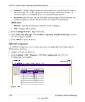
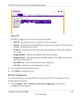
GS700TS Smart Switch Software Administration Manual • Root Port - Displays the port number that offers the lowest cost path from this bridge to the Root Bridge. This field is significant when the bridge is not the Root Bridge. The current root port is zero when the device is not connected to the network. • Root Path Cost - Displays the cost of the path from this bridge to the Root Bridge. The current root path cost is zero when the device is not connected to the network. MSTP Status • MST ID - Specifies the instance to which the VLAN is assigned. • VID - Displays the VLAN ID. 2. Enter the Bridge Priority in the provided field. 3. Select Hello Time, Max Age, Forward Delay or Spanning Tree Maximum Hops and enter the value in the provided field. 4. Click APPLY to update the device. CST Port Configuration The CSP Port Configuration screen contains parameters for assigning Common Spanning Tree (CST) values to interfaces. To configure CST ports on the device: 1. Click Switching > STP > Advanced > CST Port Configuration. The CST Port Configuration screen displays: Figure 4-23 4-35 v1.0, June 2009 Configuring Switching Settings
-
 1
1 -
2
-
3
-
4
-
5
-
6
-
7
-
8
-
9
-
10
-
11
-
12
-
13
-
14
-
15
-
16
-
17
-
18
-
19
-
20
-
21
-
22
-
23
-
24
-
25
-
26
-
27
-
28
-
29
-
30
-
31
-
32
-
33
-
34
-
35
-
36
-
37
-
38
-
39
-
40
-
41
-
42
-
43
-
44
-
45
-
46
-
47
-
48
-
49
-
50
-
51
-
52
-
53
-
54
-
55
-
56
-
57
-
58
-
59
-
60
-
61
-
62
-
63
-
64
-
65
-
66
-
67
-
68
-
69
-
70
-
71
-
72
-
73
-
74
-
75
-
76
-
77
-
78
-
79
-
80
-
81
-
82
-
83
-
84
-
85
-
86
-
87
-
88
-
89
-
90
-
91
-
92
-
93
-
94
-
95
-
96
-
97
-
98
-
99
-
100
-
101
-
102
-
103
-
104
-
105
-
106
-
107
-
108
-
109
-
110
-
111
-
112
-
113
-
114
-
115
-
116
-
117
-
118
-
119
-
120
-
121
-
122
-
 123
123 -
 124
124 -
 125
125 -
 126
126 -
 127
127 -
 128
128 -
 129
129 -
 130
130 -
 131
131 -
 132
132 -
 133
133 -
134
-
135
-
136
-
137
-
138
-
139
-
140
-
141
-
142
-
143
-
144
-
145
-
146
-
147
-
148
-
149
-
150
-
151
-
152
-
153
-
154
-
155
-
156
-
157
-
158
-
159
-
160
-
161
-
162
-
163
-
164
-
165
-
166
-
167
-
168
-
169
-
170
-
171
-
172
-
173
-
174
-
175
-
176
-
177
-
178
-
179
-
180
-
181
-
182
-
183
-
184
-
185
-
186
-
187
-
188
-
189
-
190
-
191
-
192
-
193
-
194
-
195
-
196
-
197
-
198
-
199
-
200
-
201
-
202
-
203
-
204
-
205
-
206
-
207
-
208
-
209
-
210
-
211
-
212
-
213
-
214
-
215
-
216
-
217
-
218
-
219
-
220
-
221
-
222
-
223
-
224
-
225
-
226
-
227
-
228
-
229
-
230
-
231
-
232
 |
 |
