Netgear GSM7312 FSM7326P Hardware manual - Page 11
FSM7326P Rear Panel, GSM7312 Front Panel and LEDs, Table 2-2. GSM7312 LED Description
 |
UPC - 606449030693
View all Netgear GSM7312 manuals
Add to My Manuals
Save this manual to your list of manuals |
Page 11 highlights
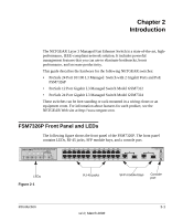
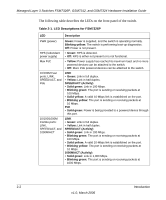
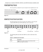
Managed Layer 3 Switches FSM7326P, GSM7312, and GSM7324 Hardware Installation Guide FSM7326P Rear Panel The rear panel has a standard AC power receptacle for the supplied power cord. Redundant power supply connector Power receptacle Figure 2-2 GSM7312 Front Panel and LEDs The following figure shows the front panel of the GSM7312. The front panel contains LEDs, RJ-45 jacks, SFP module bays, and a console port. LEDs RJ-45 jacks SFP module bays Console port Figure 2-3 The following table describes the GSM7312 LEDs on the front of the switch. Table 2-2. GSM7312 LED Description LED Power Description Green: Power supply is present and operating normally. Off: Power supply is not present. Introduction 2-3 v1.0, March 2006
-
 1
1 -
2
-
3
-
4
-
5
-
 6
6 -
 7
7 -
 8
8 -
 9
9 -
 10
10 -
 11
11 -
 12
12 -
 13
13 -
 14
14 -
 15
15 -
 16
16 -
17
-
18
-
19
-
20
-
21
-
22
-
23
-
24
-
25
-
26
-
27
-
28
-
29
-
30
-
31
-
32
-
33
-
34
-
35
-
36
-
37
-
38
 |
 |

Managed Layer 3 Switches FSM7326P, GSM7312, and GSM7324 Hardware Installation Guide
Introduction
2-3
v1.0, March 2006
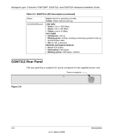
FSM7326P Rear Panel
The rear panel has a standard AC power receptacle for the supplied power cord.
GSM7312
Front
P
anel
and LEDs
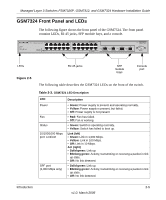
The following figure shows the front panel of the GSM7312. The front panel
contains LEDs, RJ-45 jacks, SFP module bays, and a console port.
The following table describes the GSM7312 LEDs on the front of the
switch.
Figure 2-2
Figure 2-3
Table 2-2. GSM7312 LED Description
LED
Description
Power
Green:
Power supply is present and operating normally.
Off:
Power supply is not present.
Power receptacle
Redundant power supply connector
SFP module bays
Console port
RJ-45 jacks
LEDs