Nikon 120ED Repair Manual
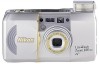
Nikon 120ED - Lite Touch 120 ED/QD Zoom Date 35mm Camera Manual
 |
UPC - 018208018581
View all Nikon 120ED manuals
Add to My Manuals
Save this manual to your list of manuals |
Nikon 120ED manual content summary:
- Nikon 120ED | Repair Manual - Page 1
FCA45001 - R. 3498. A i'MY*gg fd EP 0,1(1 C S iff;E; G. Lite:Touch FCA45001 ZOOM120 ED FCA45201 FCA45211 FCA45221 REPAIR MANUAL Nikon NIKON CORPORATION I Tokyo, Japan Printed in Japan June 2000 Copyright © 2000 by Nikon Corporation All Rights Reserved. - Nikon 120ED | Repair Manual - Page 2
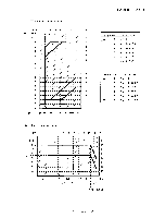
SPECIFICATIONS FCA45001--R.3498.A 1. Main specifications 2. AE coupling operation range 3. Shutter program graph 4. Manual test function 5. Zoom position 6. AF distance measurement position and photographing distance M 1 M 2 M 2 M3 -M5 M6 M 7-M 1 4 - Zoom 120 ED - - Nikon 120ED | Repair Manual - Page 3
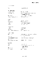
AF (Auto focus) step Exposure control Shutter type Shutter time AE (Auto exposure) coupling operation range FM coupling operation range Speed light Type Mode Guide number Charging time Camera for 35mm film f38-120mm/F5.3-10.5 3 groups zoom type and 5 groups with 7 lenses (Gl: ED lens, G5, G6: PGM - Nikon 120ED | Repair Manual - Page 4
2 . AE coupling operation range EV BV -3 1 2 3 4 5 6 7 8 EV -2 - - 1 0 _ 2 3 4 ...1 5 - 6 - - . • 7 - - 8 9 10 • 1 1 12 1 3 _ - 71- - - - - 9 10 11 1 2 13 14 15 1 6 17 18 19 20 2 1 - 22 1 4 ISO 25 50 100 200 400 800 1600 3200 FCA450O1 - R. 3498. A Zoom zone W - Nikon 120ED | Repair Manual - Page 5
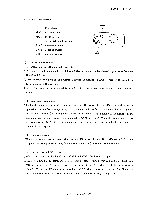
set by operating SBS, other commands are reset. When MOS is turned off, the command number is not displayed. 3 ) Display of set data ©Under the manual test mode condition, operate MOS as turning on SBS. AF data or ISO data is displayed according to the display (when a command is set) on - Nikon 120ED | Repair Manual - Page 6
exit from the test mode. The test mode is canceled. ©Even if the lens barrel is driven at W end with the timer at "2 minutes", the manual test mode is not canceled. ®If the camera back is opened while the bulb is opened, the bulb keeps open. ©Even if the test mode - Nikon 120ED | Repair Manual - Page 7
FCA45001 - R.3498.A ( 2 ) Test command list @The following test commands are provided. When a command number is selected, a command marked with "O" is valid. Command No Command Display Deails of check 1 2 3 4 5 Bulb O setting When set AF distance data Result The lens barrel moves to the edge - Nikon 120ED | Repair Manual - Page 8
FCA45001 - R. 3498. A 4 ) ISO set value C)2 digits of the film counter are used and the set ISO value is displayed as follows. The set ISO value 50 1 0 0 2 0 0 4 0 0 8 0 0 1 6 0 0 3 2 0 0 Displayed data 05 10 20 40 8 0 1 6 32 5 . Zoom position Zone Re 1 (W) 2 (M1) 3 (M2) 4 (M3) 5 (M4) 6 (T) - Nikon 120ED | Repair Manual - Page 9
FCA45001 - R. 3498. A 6 . AF distance measurement position and photographing distance Edge Display W M 1 M 2 M 3 M 4 T Distance [m] Distance [m] Distance [m] Distance [m] Distance [m] Distance [m] 0 00 co 00 co oo CO 03 1 0 1 80.975 110. 247 115.593 129.399 145. 698 186. 847 2 - Nikon 120ED | Repair Manual - Page 10
FCA45001 - R. 3498. A Edge 3 6 3 7 3 8 3 9 4 0 4 1 4 2 4 3 4 4 4 5 4 6 4 7 4 8 4 9 5 0 5 1 5 2 5 3 5 4 5 5 5 6 5 7 5 8 5 9 60 6 1 6 2 6 3 6 4 6 5 6 6 6 7 6 8 6 9 7 0 7 1 Display 2 4 2 5 2 6 2 7 2 8 2 9 2 A 2 b 2 C 2 d 2 E 2 F 3 0 3 1 3 2 3 3 3 4 3 5 3 6 3 7 3 8 3 9 3 A 3 b 3C 3 d 3 E 3 F 4 0 4 1 4 - Nikon 120ED | Repair Manual - Page 11
FCA45001 - R. 3498. A Edge 7 2 7 3 7 4 7 5 7 6 7 7 7 8 7 9 8 0 8 1 8 2 8 3 8 4 8 5 8 6 8 7 8 8 8 9 9 0 9 1 9 2 9 3 9 4 9 5 9 6 9 7 9 8 9 9 1 00 1 01 1 02 1 03 1 04 1 0 5 1 0 6 1 07 Display 4 8 4 9 4 A 4 b 4 C 4 d 4 E 4 F 5 0 5 1 5 2 5 3 5 4 5 5 5 6 5 7 5 8 5 9 5 A 5 b 5 C 5 d 5 E 5 F 6 0 6 1 6 2 6 - Nikon 120ED | Repair Manual - Page 12
FCA45001 - R. 3498. A Edge 1 08 1 09 1 1 0 1 1 1 1 1 2 1 1 3 1 1 4 1 1 5 1 1 6 1 1 7 1 1 8 1 1 9 1 20 1 2 1 1 22 1 23 1 24 1 25 1 26 1 27 1 28 1 29 1 30 1 31 1 32 1 33 1 34 1 35 1 36 1 37 1 38 1 39 1 40 1 41 1 42 1 43 Display 6 C 6 d 6 E 6 F 7 0 71 7 2 7 3 7 4 7 5 7 6 7 7 7 8 7 9 7 A 7 b 7 C 7 d 7 - Nikon 120ED | Repair Manual - Page 13
FCA45001 - R. 3498. A Edge 1 44 1 45 1 46 1 47 1 48 1 49 1 50 1 51 1 52 1 53 1 54 1 55 1 56 1 57 1 58 1 59 1 60 1 61 1 6 2 1 63 1 64 1 65 1 66 1 6 7 1 68 1 69 1 70 1 71 1 7 2 1 73 1 74 1 75 1 76 1 77 1 78 1 79 Display 9 0 9 1 9 2 9 3 9 4 9 5 9 6 9 7 9 8 9 9 9 A 9 b 9 C 9 d 9 E 9 F A 0 A 1 A 2 A 3 - Nikon 120ED | Repair Manual - Page 14
FCA45001 - R. 3498. A Edge 1 8 0 1 8 1 1 8 2 1 8 3 1 8 4 1 8 5 1 8 6 1 8 7 18 8 1 8 9 19 0 1 9 1 1 9 2 1 9 3 1 9 4 1 9 5 1 9 6 1 9 7 1 9 8 1 9 9 2 0 0 2 0 1 2 0 2 2 0 3 2 0 4 2 0 5 2 0 6 2 0 7 2 0 8 2 0 9 2 1 0 2 1 1 2 1 2 2 1 3 2 14 2 1 5 Display b 4 b 5 b 6 b 7 b 8 b 9 b A b b b C b d b E b F C - Nikon 120ED | Repair Manual - Page 15
FCA45001 - R. 3498. A Edge 2 1 6 21 7 21 8 21 9 2 2 0 2 2 1 2 2 2 2 2 3 2 2 4 2 2 5 2 2 6 2 2 7 2 2 8 2 2 9 2 3 0 2 3 1 2 3 2 2 33 2 3 4 2 3 5 2 3 6 2 3 7 2 3 8 2 3 9 2 4 0 2 4 1 2 4 2 2 4 3 2 4 4 2 4 5 2 4 6 2 4 7 2 4 8 2 4 9 2 50 2 5 1 Display d 8 d 9 d A d b d C d d d E d F E 0 E 1 E 2 E3 E4 E5 - Nikon 120ED | Repair Manual - Page 16
FCA45001 - R. 3498. A Edge 2 5 2 2 5 3 2 5 4 2 5 5 2 5 6 2 5 7 2 5 8 2 5 9 2 6 0 2 6 1 2 6 2 2 6 3 2 6 4 2 6 5 2 6 6 2 6 7 2 6 8 2 6 9 2 7 0 27 1 2 7 2 Display F C F d FE FE 1 0 0 10 1 10 2 1 0 3 1 0 4 10 5 1 0 6 1 0 7 1 0 8 1 0 9 1 OA 1 0 b 1 0 C 10 d 1 0 E 1 0 F 1 1 0 W M 1 M 2 M 3 M 4 T - Nikon 120ED | Repair Manual - Page 17
DISASSEMBLING REAR COVER ELECTRIC DISCHARGE FROM MAIN CAPACITOR FRONT COVER MAIN FPC SB UNIT, MAIN CAPACITOR CAMERA BACK FINDER ASSEMBLY DATE MODULE UNIT, DIOPTER COMPENSATION DIAL LENS BARREL UNIT PANORAMA LEVER, PANORAMA UNIT FILM ADVANCE GEAR, SPOOL COVER SPOOL, FILM ADVANCE MOTOR DX CONTACT, - Nikon 120ED | Repair Manual - Page 18
static electricity from the main condenser according to the instruction in the repair manual after removing the rear cover Note : CDBe sure 1. DISASSEMBLING REAR COVER (Eyepiece) • Rear cover Caut i on : Don't touch the eyepiece unit directly. Use a special cloth for cleaning. Refer to TECHNICAL - Nikon 120ED | Repair Manual - Page 19
ELECTRIC DISCHARGE FROM THE MAIN CAPACITOR FCA45001--R.3498.A • Discharge the electricity between the both terminals of Xe tubes. • For the electric discharge, employ the resistor of approximately 2 k Q / 5 W. Discharging resistor 0 00 ri FRONT COVER O #619 0 0O0 °oo Black(Front cover) 8 - - Nikon 120ED | Repair Manual - Page 20
FCA450-R0.13498A. MAIN FPC Solde bridge Black 1 D' 51 0 /OJ Black(SB unit) Red(SB unit) Connector O # 404,7,1 Tape Pc Tape Black(Cathode on a battery) 0 0 ° D 0 0 0 0 Blue (Re d - e ye reduction lamp) 0 )O1 t1 O 00 Black(Cathode on a battery) Orange(Anode on a ba_.t). tery) Orange( - Nikon 120ED | Repair Manual - Page 21
• • • Solder bridge / I O 1 • a • • • S. •••• S 1 I / • • • • • •••• 0 0 0 0 0 0 0 FCA45001 -R. 3498. A I. • 4 1° Solder bridge # 133 et) #818 X 2 SB UNIT, MAIN CAPACITOR #817 B2141 # 144 # 143 1S__ #88188x22 # 308 B2142 0 000 Orange(Battery contact) #307 0 0 0 0 - Nikon 120ED | Repair Manual - Page 22
CAMERA BACK FCA45001-R. 3498. A # 162 Camera back a. 4°4144t04'411k- • . - - Nikon 120ED | Repair Manual - Page 23
FCA45001-R. 3498. A DATE MODULE UNIT, DIOPTER COMPENSATION DIAL 814 11719 B1028 814 [Non-QD type )T11 #726 #51e8 v, tt.1 #520 519 '#\ c'N # 522 # 521 104.11111f0 4b4 1 LENS BARREL UNIT 0 0 0 0 0 0 a czo 0 Lens barrel unit IJ 0 0 663 x 4 827 x 3 g823 - D 6 • Zoom 120 ED - Nikon 120ED | Repair Manual - Page 24
PANORAMA LEVER, PANORAMA UNIT # 148 01 0 0 FCA45001 -R. 3498. A 0 0 0 0 0 0 B404 B405 #402 # 408 #803 B1006 0 #401 6r. o 0 O 0 0 0 0 #407 #826 - D7 • ZOO112 120 ED - - Nikon 120ED | Repair Manual - Page 25
FILM ADVANCE GEAR, SPOOL COVER 4819 806 (;) B228 CD FCA45001-R. 3498. A I. iQ 0 I I hr I°: or m;•-•4•1 0 # 135 B132 b 4231c) B211 (!! ) B222 ( i ) 4208 11 209 O 4210 0 #210 4231 4 232 4 219 4313 q9 4 816 x 2 4 235 0 a a 0 a 0 0 0 8 4804 x 3 225 0 a 0 a Relay FPC - D8 • - Nikon 120ED | Repair Manual - Page 26
SPOOL, FILM ADVANCE MOTOR a~ # 224 IMO fkoL,.. CO • FCA45001-R. 3498. A # 220 # 207 o 0 Film advance motor unit # 819 x 2 # 807 DX CONTACT, FILM HOLDER, TRIPOD SOCKET # 811 # 139 B253 I II #119 O 45 #825x2 # 140 #819x2 #134x4 D9 • Zoom 120 ED - - Nikon 120ED | Repair Manual - Page 27
SB LEVER, GEAR COVER FCA45001 -R. 3498. A # 801x 4 CD C1) B603 0 4 304 # 806 00 4644 0 O # 806 4 305 # 642 0 0 0 0 - 4 643 #661 (Solder bridge) # 641 REMOVAL OF THE LENS BARREL %.,e JT O 0 0 0 0 c'© # 655 #659 # 652 4 653 (`10 • 4 654 C 4 655 0 #813x2 B660 - D1 0 • Zoom 120 ED - Nikon 120ED | Repair Manual - Page 28
HELICOID RING, CAM RING •-• -, •P> #628 .4() CD#629 ) ) ) FCA45001--R.3498.A #623 #622 #616x 3 B603 4 #602 - D 1 1 • Zoom 120 ED - - Nikon 120ED | Repair Manual - Page 29
FCA45001-R. 3498. A #626 #606 FPC HOLDER PLATE #8O5x 3 OD- OD #647x 3 1011101■0210110MM #646x 3 1 st LENS GROUP #611 4634 SHUTTER UNIT, 3rd LENS HOUSING UNIT B61O // O 3rd lens housing unit #615X 3 Caution : In B61O, the 2nd lens group is already centered while it includes the shutter. - Nikon 120ED | Repair Manual - Page 30
ASSEMBLING/ADJUSTMENT 1 . LENS BARREL SUTTER UNIT, 3rd LENS HOUSING UNIT 1st LENS GROUP FPC HOLDER PLATE HELICOID RING, CAM RING LENS BARREL MOTOR, LENS BARREL GEAR GROUP LENS BARREL FPC FINDER CAM GROUP LENS BARREL SB LEVER 2. REAR BODY DX CONTACT, FILM HOLDER, TRIPOD SOCKET SPOOL, FILM ADVANCE - Nikon 120ED | Repair Manual - Page 31
2. ASSEMBLING/ADJUSTMENT 1 . LENS BARREL SHUTTER UNIT, 3rd LENS HOUSING UNIT #612 B610 FCA45001-R. 3498. A ZCC C) 3rd lens housiT tilt #615x 3 Caution: In B610, the 2nd lens group is already centered while it includes the shutter. Don't disassemble B610 to keep the accuracy. All the parts are - Nikon 120ED | Repair Manual - Page 32
convex part CFD- 005.5H #606 \ , Setting position ®Put in #626 and turn #605 in the arrow mark direction. #626 #605 ©Turn #605 till it touches the stopper and make sure that the 1st lens group chamber is protruded by approx. 17.5mm. 17.5mm 1 - A2 • Zoom 120 ED - - Nikon 120ED | Repair Manual - Page 33
FCA45001--R.3498.A B606 CFD - 005.5H B603 The widest convex part a • • • • #602 CFD- 005.5H j (Setting position) ; I- Illommom • The widest groove • 0 Set the lens barrel to the TELE position. © Fit the setting positions as illustrated above. 0 Turn #602 in the arrow mark direction and fit - Nikon 120ED | Repair Manual - Page 34
LENS BARREL MOTOR, LENS BARREL GEAR GROUP FCA45001--R.3498.A #601 0 #820 #311 B650 0 0 #656 0 #815x2 #658 X 0 • Apply G474C to gears and gear shafts. [Reference] If one of the two gears (#655) is removed, the work is easier. The procedures in the subsequent pages are described on the - Nikon 120ED | Repair Manual - Page 35
LENS BARREL FPC FCA45001 - R. 3498. A 0 4 ./. 0 0 C) 0 o O 0 0 # 1029 Solder bridge 0 B1004 CD 0 0 4 ./ 0 o 0 0 0 o 0 Solder bridge - A5 • Zoom 120 ED - - Nikon 120ED | Repair Manual - Page 36
FCA45001 -R. 3498. A FINDER CAM GROUP # 812 # 544 B541 Insert into the clearance. B503 Fit to the rear groove. 0 e ,,,, -- i • G474C # 540 LENS BARREL f' O B671 r .40 # 811 O 0 O 0 CFD - 005.5H #812 (Setting position) o C o 0O 0 O 601 O 0 O O • After setting, if - Nikon 120ED | Repair Manual - Page 37
-R. 3498. A # 801 x4 0 13503 00 B603 O 0 0 O # 661 0 Turn B503 in the arrow mark direction till it touches the stopper. 0 Mount B603. (Inspection) Operate the lens barrel unit manually and make sure that B503 is actuated in a coupling operation. (Solder bridge) SB LEVER G474C # 644 \ as, 642 - Nikon 120ED | Repair Manual - Page 38
FCA45001 -R. 3498. A c9B253 2. REAR BODY DX CONTACT, FILM HOLDER, TRIPOD SOCKET 4 160 • Regard the hatching section B253 as standard. 139 4 811 0 #15 # 119 0 0 0 0 0 825x 2 140 4 819x 2 252 0 0 # 134 X 4 0 O O OO 0 4 252 • Fit these end faces to each other. SPOOL, FILM ADVANCE - Nikon 120ED | Repair Manual - Page 39
SPOOL COVER, FILM ADVANCE HOLDER #819 #806 228 G;) FCA45001 -R. 3498. A I Pass the red and black wires of the film advance motor through the hole on the rear of B228 to outside. 0 0 # 135 0 0 C -8008B et0 # 816 x 2 FILM ADVANCE GEAR GROUP #313 B132 0 z4, 0 #231 B222 () # 208 #209 0 #210 - Nikon 120ED | Repair Manual - Page 40
Qo # 225 FCA45001 -R. 3498. A Relay FPC # 235 # 804 X 3 O O O O O O O O O O Relay FPC 219 -- A 1 0 • Zoom 120 ED - Nikon 120ED | Repair Manual - Page 41
PANORAMA LEVER, PANORAMA UNIT FCA45001-R. 3498. A to sliding surfaces CFD-005.5H \B 1006 0 0 #401 # 2546.\ .50 0 0 0 0 0 0 0 0 0 # 407 # 148 0I I ' 0 0 0 0 0 0 0 0 to sliding surf.ices CFI) -005.514 0 0 B405 to sliding surfaces CFI) -005.5H B404 1:4402 803 4 408 - A 1 1 • Zoom 120 - Nikon 120ED | Repair Manual - Page 42
BATTERY CONTACT FCA45001 -R. 3498. A .., B141 #a817 HOW TO ASSEMBLE THE LENS BARREL AND THE REAR BODY 0 0 00 0 0 0 0 Lens barrel unit 1:663x 4 /7 827 x3 0 0 0 D 823 A 1 2 • Zoom 120 EL) - Nikon 120ED | Repair Manual - Page 43
DATE MODULE UNIT FCA45001-R. 3498. A #814 # 719 B1028 #814 [Non -QD type] #726 r. 41 4 I %t4'444t: ! it • I foLr twOr/if" #731 DIOPTER COMPENSATION DIAL # 520 #518 0. N 522 G 7 C 0 #521 C C C 0 0 - A 1 3 • Zoom 120 ED - - Nikon 120ED | Repair Manual - Page 44
FCA45001-R. 3498. A FINDER ASSEMBLY # 819x 2 Fit the convex part of the diopter compensation lens. Panorama lever 0 0 0 0 0 0 O O 0 OSet the lens barrel to the TELE side. ©Set the panorama lever to the panorama side. ©Mount the finder assembly. [Check] When the diopter compensation dial, - Nikon 120ED | Repair Manual - Page 45
CAMERA BACK FCA45001-R.3498.A #162 Camera back CD. 'II • t, 1; (*Al( SB UNIT, MAIN CAPACITOR 000 Orange(Battery contact) #817 #308 CFD- 005.5H IG103I B2141 B2142 O #712 0 0 1# 303 0 Gray(Relay FPC) 0 #312 g# 306 Solder bridge - A 1 5 • Zoom 120 ED - - Nikon 120ED | Repair Manual - Page 46
MAIN FPC 0 FCA45001 -R. 3498. A ot, OO ti 0 • • ,• • 0 • 0 0 (Main FPC) Fold outside Fold inside Solder bridge / / I O 1 0 1, • • •., •., • • • I I / / 1 1 / O 0 0 0 F 0 0 144 0 (Relay FPC) (Main FPC) /(Lens barrel FPC) - A 1 6 • Zoom 120 ED Solder bridge 4 133 :i18 x2 - Nikon 120ED | Repair Manual - Page 47
FCA45001-R. 3498. A ARRANGE WIRES Black(Cathode on a battery) (TA-0006S) (3 wires from the SB unit) 0 Tr KMoili O OM UP% I I I0 O O O O OO cr,A$ O :pi m®coo icor ;; O Blue(Red-eye reduction lamp) Black(Cathode on a battery) Orange(SB PCB) 0 O Orange(Anode on a battery) O all 0 O - Nikon 120ED | Repair Manual - Page 48
FCA45001-R. 3498. A CAMERA BACK LOCK-RELEASE LEVER Connect the connector. # 817 # 137 G474C a # 138 # 136 # 818 Solder bridge Black J000 of Black(SB unit) Red(SB unit) - A 1 8 • Zoom 120 ED - O 0 Zt - 08 - Nikon 120ED | Repair Manual - Page 49
FRONT COVER 0 MI • 000 J Black(Front cover) O #519 O 11.0 re --,1-2.40,41 # 619 it 0." • FCA45001 -R. 3498. A Front cover it Caution: If one gear (#655) has been a removed in Page A4, set it at this time. 8 #824x3 - A 1 9 • ZOO171 120 ED - - Nikon 120ED | Repair Manual - Page 50
124 C- 8008B #824 x 4 clA O 0 FCA45001--R.3498.A • #124 is used only for the body without panorama. NI • BATTERY CHAMBER COVER Caution : Don't touch the eyepiece unit directly. Use a special cloth for cleaning. Refer to TECHNICAL INFORMATION Ref. No. 99086. 0 0 B171 C -8008B # 629 # 628 # 733 - Nikon 120ED | Repair Manual - Page 51
3. INSPECTION AND ADJUSTMENT HOW TO CONNECT THE CAMERA WITH THE COMMUNICATION TOOL(S) FCA45001 -R. 3498. A CI 0 0 J15368 0 0, J15325 * Set the switch 1 to NEW J15278 A 2 1 • Zoom 120 ED - - Nikon 120ED | Repair Manual - Page 52
Collimator focusing position Location where vertical line changes from blue to red. • Inspection in manual inspection mode (DSee the above-mentioned to set inspection tool. ©Set the camera to bulb and infinity focus(00h) in manual inspection mode (see page M3,4,5) ©Read the - Nikon 120ED | Repair Manual - Page 53
set to ISO 100 as well. • Inspection in the manual inspection mode 1. Check the EV by with the manual inspection mode. (Refer to page M3,4,5) 2. Check the software and then connect the camera with PC. 2. Follow the instructions on the PC screen for adjustment. AF INSPECTION AND ADJUSTMENT • - Nikon 120ED | Repair Manual - Page 54
ANY CERTAIN ADJUSTMENT ITEM(S) TO BE REQUIRED WHEN REPLACING FCA45001 - R . 3498. A MAIN FPC Inspection and adjustment of backfocus AE inspection and adjustment AF inspection and adjustment Delaytimeinthe shutter mechanism 0 0 0 0 SHUTTER UNIT 0 0 0 LENS BARREL UNIT 0 ENCODER FPC - Nikon 120ED | Repair Manual - Page 55
MI/ELECTRIC CIRCUIT voidao El M El 24 4'.., F PC 1- 0 A-A& I- 9 )f-A& EEPROM DATA FCA45001 -R. 3498. A E 1 E2 E 3-E 5 E 6-E 7 E 8-E 9 E10 CONTENTS WIRING CIRCUIT DIAGRAM MAIN F PC SB P.C. B. TRIGGER P. C. B. EEPROM DATA E1 E2 E 3-E 5 E 6-E 7 E 8-E 9 E1 0 - E 0 • Zoom 120 ED - - Nikon 120ED | Repair Manual - Page 56
Zoom SW X-1, SW l llz O 0 A : 1 135 o 11 138 1 137 Black X N Red Ma in condenser 230uF Zoom SW FPC FPC 1005 Panorama FPC co /\•,J 77FP C Main FPC unit ;4 -(>FPC35X4 Red-eye reduction lamp * 1 128 1128 0 Date module 5-.- H 1028 Zebra connector LCD •E'"7- 2z7 0 FCA45001-R. 3498. A AE,AF - Nikon 120ED | Repair Manual - Page 57
Fi lm advance rotor #1003 -O- tp Outer communication terminal 911111441il sf Veit eve reduction Ito', 00000 .csarsiol 04 Reverse mount INA Shutter FPC II 1004 /19101- I Photo ref lector 4 sh -"C toit-i61 pou-SMS 502-M6 .o 2-1Pri v9 -9 - 01, Shutter rotor Zoom motor0 X -L 01 as - Nikon 120ED | Repair Manual - Page 58
FCA45001-R. 3498. A MAIN FPC Ul CNI R00 C5 R15 R13 C15 C16 R19 011 C101 07 R12 N880657 R82 C18 012 013 04 048230317 lko 331 1ko lko a 047LF a 1uF 110 MA741MK 0.CFAF UW:21N 1ko AR-332 lko 0.01LF NA741W mA4S713 UN611N 001800 1090 1062 1073 1073 1044 1041 1072 1103 1043 1035 1073 1011 1090 1045 - Nikon 120ED | Repair Manual - Page 59
MAIN FPC TP-RCD TP-MXC2 TP-MXC1 To-RG TP-DCC TP-PON XL4-ZUS XL4-ZDS XL4-GND2 XL4-GND1! WL-GND XL5-NL1 XL5-SBO TP-SBS SBS MUS MOS TP-MOS TP-MUS O0 0 TP-CLK TP-CEN TP-EXT TP-AFD TP-END TP-AFRST 0 >< Z CD >< Lli LJ L..1 C...) 6 -; -; 1= == I= L) L.) L) 0 I I .;1 Nevin TN1 DGND CN1- - Nikon 120ED | Repair Manual - Page 60
)c 4 >7 I,* MAIN FPC XL6-DGND XL6-PAR XL3-VC XL3-DGND XL3-VDD XL8-RMIN XL8-DGND XL8-PIN ... FCA45001-R. 3498. A XL.:'-D1 XL3-D2D3 XL3-04 /XI 3-D5D6 / IXL3-07 J 0 0 DGND DX2 DX3 DX4 O 7. 0 6 WL-GND 0 0 (OM 0 NC 0 0 0 .,,,-,----- - c '--__ 4 'g, DGND H.4:'\32 - lilgt S41_ I-___ - Nikon 120ED | Repair Manual - Page 61
SB P. C. B. FCA45001-R. 3498. A 1141 D203 1108 D201 1107 270V D202 1108 -1- D i + D + C + + A + 1156 R206 471 - Nikon 120ED | Repair Manual - Page 62
F,izi* ata SB P. C. B. FCA45001-R. 3498. A + I r ( O 1037 Q201 1060 C205 4700pF 11 44 TI 1141 A 1:Ii3Nal-lELT Reverse parts mount figure -E 7 • Zoom 120 ED -- - Nikon 120ED | Repair Manual - Page 63
915-a* TRIGGER P. C. B. C202 105-n 0.033uF D204 1040 0203 1058 0.47uF 0 U u U FCA45001-R. 3498. A 1142 1153 R203 IMO 1152 R202 IK11 1151 R201 1000 Surface parts mount figure -E 8 • Zoom 120 ED - - Nikon 120ED | Repair Manual - Page 64
FCA45001-R. 3498. A 1145 T2 1142 0 Reverse parts mount figure -E 9 • Zoom 120 ED - Nikon 120ED | Repair Manual - Page 65
EEPROM DATA Address 0 [OH] I 37 [25H] 38 [26H] 1 47 [2FH] 48 [30H] 60 [3CH] 61 [3DH] I 64 [40H] 65 [41H] I 72 [48H] 73 [49H] 122 [7AH] 123 [7BH] I 184 [B8H] 185 [B9H] 196 [C411] 197 [C5H] I 292 [124H] 293 [125H] 295 [127H] 296 [128H1 507 [1FBH] 508 [1FCH] 51 1 [IFFII] )3 24 -7 $11 00: CAMERA - Nikon 120ED | Repair Manual - Page 66
INSPECTION STANDARD AND TOOLS (1) Inspection standard (2) Tools FCA45001-R.3498.A R 1 T 1 CONDITION FOR INSPECTION Normal temperature : 2 5 ± 5°C (Relative humidity : 6 5 ± 2 0%) Power source : 3.0 + 0.0 3 V 5 A or more at O.5 Q load Light source : Surface light source 2.8 5 4 ° K K coefficient : - Nikon 120ED | Repair Manual - Page 67
FCA45001 - R . 3498. A 1 1 Standard of inspection Item Picture size Photogra phy Standard of judgment Length: Width. 24' 0 - 0. O. 8 3 MM 36• 0 +0 - . . 83 Mill Short side of panorama• 13' 3 +2 - O . . 7 3 Mn Picture position (Full size) DEIDOODO 0.2mm or more Method and - Nikon 120ED | Repair Manual - Page 68
FCA45001 - R.3498.A AE accuracy Item Standardofjudgment Method and tools The demands of the following table must be fulfilled. AE tester EF-511N • Set the camera near the luminance surface of the AE tester and EF8000 measure the aperture surface at each luminance. • It is permitted to check - Nikon 120ED | Repair Manual - Page 69
charging with a fresh battery for 18 seconds, Fresh battery ( ISO 100 • m) flash the speed light within 1 second and measure the Speed light guide number. FULL:G No. 14±0.4E V meter Perform release continually in 2 times/sec under the Standard uncharged condition and obtain the minimum value - Nikon 120ED | Repair Manual - Page 70
Motor drive FCA45001 - R.3498.A Item Fi 1m advance Winding Standard of judgment Operating time Operating electric current Within 1.5 sec Within 600mA Method and tools Oscilloscope Constant-voltage power supply Rewinding Within 50 sec Film Counter display Winding time for 36th pictures • - Nikon 120ED | Repair Manual - Page 71
[2] TOOLS FCA45001 - R. 3498. A 1. Major general tools and tester Tool No. J15369-1 J15369-2 J15369-3 J15369-4 J15369-5 J19019 J19036 J19042 J15291 J15368 J18313A J18313B J18313C J18313D Name DC regulated power supply Digital multimeter AF ADJUSTMENT CHART AF ADJUSTMENT CHART AF ADJUSTMENT CHART
-
 1
1 -
 2
2 -
 3
3 -
 4
4 -
 5
5 -
 6
6 -
 7
7 -
8
-
9
-
10
-
11
-
12
-
13
-
14
-
15
-
16
-
17
-
18
-
19
-
20
-
21
-
22
-
23
-
24
-
25
-
26
-
27
-
28
-
29
-
30
-
31
-
32
-
33
-
34
-
35
-
36
-
37
-
38
-
39
-
40
-
41
-
42
-
43
-
44
-
45
-
46
-
47
-
48
-
49
-
50
-
51
-
52
-
53
-
54
-
55
-
56
-
57
-
58
-
59
-
60
-
61
-
62
-
63
-
64
-
65
-
66
-
67
-
68
-
69
-
70
-
71
 |
 |
FCA45001
-
R
.
3498
.
A
i'MY*gg
fd
EP
0,1(1
C
S
iff
;E;
G.
Lite
:Touch
FCA45001
FCA45201
ZOOM120
ED
FCA45211
FCA45221
REPAIR
MANUAL
Nikon
I
NIKON
CORPORATION
Tokyo,
Japan
Copyright
©
2000
by
Nikon
Corporation
All
Rights
Reserved.
Printed
in
Japan
June
2000