Nokia IP265 Security Guide - Page 7
Module Interfaces - reset
 |
View all Nokia IP265 manuals
Add to My Manuals
Save this manual to your list of manuals |
Page 7 highlights
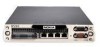
2.3 Module Interfaces The security platforms provide a number of physical ports: Ethernet Ports (standard) Auxiliary Port (Disabled) Console Port I/O Option Slots (for adding 1000 BaseT or 1000 Mbps fiber Ethernet, V.35, or X.21 protocol options) PCMCIA Slots (secured with Tamper Seals) Power Switch Reset Switch Status LEDs Power Fault Ethernet Port status (green indicates connection, yellow blinking indicates data being transmitted) IP260/IP265 4 1 1 N/A 2 (enabled) 1 1 1 1 1 IP1220/IP1260 4 1 1 3 2 (disabled) 1 1 1 built in, 1 per optional PMC NIC card) 1 1 built in, additional depending on number of I/O option cards installed Descriptions of the status LEDs © Copyright 2005, 2006, 2007 Nokia Page 7 of 43 This document may be freely reproduced and distributed whole and intact including this Copyright Notice.
-
 1
1 -
 2
2 -
 3
3 -
 4
4 -
 5
5 -
 6
6 -
 7
7 -
 8
8 -
 9
9 -
 10
10 -
 11
11 -
 12
12 -
13
-
14
-
15
-
16
-
17
-
18
-
19
-
20
-
21
-
22
-
23
-
24
-
25
-
26
-
27
-
28
-
29
-
30
-
31
-
32
-
33
-
34
-
35
-
36
-
37
-
38
-
39
-
40
-
41
-
42
-
43
 |
 |
