NordicTrack Cx 1055 Elliptical Exerciser English Manual - Page 6
Next, insert the Short Clevis Pin 118 through the U
 |
View all NordicTrack Cx 1055 Elliptical Exerciser manuals
Add to My Manuals
Save this manual to your list of manuals |
Page 6 highlights
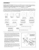
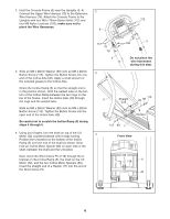
2. Hold the Console Frame (6) near the Uprights (3, 4). 2 Connect the Upper Wire Harness (75) to the Extension Wire Harness (76). Attach the Console Frame to the Uprights with four M8 x 76mm Button Bolts (112) and 112 four M8 Nylon Locknuts (102); make sure not to pinch the Wire Harnesses. 6 3. Slide an M8 x 28mm Washer (99) onto an M8 x 20mm Button Screw (113). Tighten the Button Screw into one end of the Incline Axle (40). Apply a small amount of the included grease to the Incline Axle. Orient the Incline Ramp (5) so that the straight end is in the position shown. Hold the welded tube on the bottom of the Incline Ramp between the two rings on the top of the Frame. Insert the Incline Axle (40) through the rings and the welded tube. Slide an M8 x 28mm Washer (99) onto an M8 x 20mm Button Screw (113). Tighten the Button Screw into the open end of the Incline Axle (40). Be careful not to scratch the Incline Ramp (5) during steps 4 through 6. 4. Using your fingers, turn the shaft on top of the Lift Motor (42) counterclockwise until it stops turning. Position the U-bracket on the bottom of the Incline Ramp (5) over the end of the shaft as shown. Next, hold an Incline Motor Spacer (60) on each side of the shaft, between the shaft and the U-bracket. Next, insert the Short Clevis Pin (118) through the Ubracket on the Incline Ramp (5), the shaft on the Lift Motor (42), and the two Incline Motor Spacers (60). Insert the straight end of a Hairpin (71) into the end of the Short Clevis Pin. 112 75 76 4 3 3 102 Do not pinch the wire harnesses during this step. 5 Straight 40 99 113 End Grease 113 99 1 4 Front View 60 71 118 5 42 6
-
 1
1 -
 2
2 -
 3
3 -
 4
4 -
 5
5 -
 6
6 -
 7
7 -
 8
8 -
 9
9 -
 10
10 -
 11
11 -
 12
12 -
13
-
14
-
15
-
16
-
17
-
18
-
19
-
20
-
21
-
22
-
23
-
24
-
25
-
26
-
27
-
28
 |
 |
