NordicTrack Sl705 Bike English Manual - Page 5
Upper Wire Harness.
 |
View all NordicTrack Sl705 Bike manuals
Add to My Manuals
Save this manual to your list of manuals |
Page 5 highlights
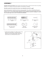
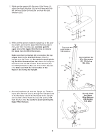
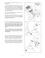
2. While another person lifts the rear of the Frame (1), attach the Rear Stabilizer (16) to the Frame with four M8 x 40mm Button Screws (54) and four M8 Split Washers (55). 2 1 16 3. While another person holds the Upright (2) in the position shown, connect the Upper Wire Harness (42) to the Lower Wire Harness (43). Carefully pull the upper end of the Upper Wire Harness to remove the slack from the Wire Harnesses. Make sure that the Upright (2) is turned so the top slopes down in the direction shown. Slide the Upright onto the Frame (1). Be careful to avoid pinching the Wire Harnesses (42, 43). Attach the Upright to the Frame with four M8 x 44mm Button Screws (77), four M8 Split Washers (55), and three 6.6mm Spacers (76). Make sure that the curved sides of the Spacers are facing the Upright. 55 55 54 54 3 Top must slope down in this direction. 2 76 77 55 1 Do not pinch the Wire Harnesses (42, 43) during this step. 76 55 77 42 43 4. Hold the Handlebar (3) near the Upright (2). Feed the 4 Upper Wire Harness (42) up through the indicated hole in the Handlebar. Attach the Handlebar to the Upright with two M8 x 25mm Patch Screws (59) and two M8 Split Washers (55). Be careful to avoid pinching the Upper Wire Harness. Do not pinch the Upper Wire Harness (42) during this step. 59 55 Hole 3 42 2 5
-
 1
1 -
 2
2 -
 3
3 -
 4
4 -
 5
5 -
 6
6 -
 7
7 -
 8
8 -
 9
9 -
 10
10 -
 11
11 -
12
-
13
-
14
-
15
-
16
-
17
-
18
-
19
-
20
-
21
-
22
-
23
-
24
 |
 |
