| Section |
Page |
| FEDERAL COMMUNICATIONS COMMISSION NOTICE |
3 |
| Modifications |
3 |
| CANADIAN NOTICE |
4 |
| AVIS CANADIEN |
4 |
| EUROPEAN NOTICE |
4 |
| CLASS 1 LASER PRODUCT |
5 |
| Unpacking the Base Engine |
6 |
| 1. Open the Cover Assy Front (PL1.1.9). |
6 |
| 2. Catch in the handle of the Holder BTR:L.And pull out the Holder BTR:L from the Base Machine to... |
6 |
| 3. Catch in the handle of the Holder BTR:R.And pull out the Holder BTR:R from the Base Machine to... |
6 |
| Contents |
7 |
| Introduction |
9 |
| About this Manual |
10 |
| Sections 1 The Service Flowchart |
13 |
| 1. Service Flowchart |
14 |
| 1. Verify that the reported problem does exist. |
15 |
| 2. Check for any error codes. |
15 |
| 3. Execute three test prints. |
15 |
| 4. Take note of any print quality problems in the three test prints. |
15 |
| 5. Take note of any mechanical or electrical abnormalities that are present. |
15 |
| 6. Take note of any unusual noise or smell coming from the printer. |
15 |
| 7. When you have identified the problem, go to the next block that is listed in the Service Flowc... |
15 |
| 1. Switch OFF the printer power. |
15 |
| 2. Disconnect the AC power cord from the wall outlet. |
15 |
| 3. Disconnect the power cord from the printer. |
15 |
| 4. Open the Cover Assy Front. |
15 |
| 5. Remove the CRU. |
15 |
| 6. Inspect for and remove any foreign matter such as paper clips, staples, scraps of paper, paper... |
15 |
| 7. Clean the interior with a lint–free cloth, dampened slightly with cold water. |
15 |
| 8. Clean the rubber rollers with a lint-free cloth, dampened slightly with cold water. Use a clea... |
15 |
| 9. Clean the Laser Scanner window with a soft, dry, lint-free cloth. |
15 |
| 10. Use canned air to clean the BTR. |
15 |
| 11. While cleaning, inspect the interior of the printer for damaged wires, loose connections, ton... |
15 |
| 12. If the CRU appears excessively dirty or obviously damaged, replace it with a new one. |
15 |
| 13. When you have finished cleaning the printer, go to the next block that is listed in the Servi... |
15 |
| 1. Reinstall all of the covers that you removed while servicing the printer. |
16 |
| 2. Check that the original error code is gone and there are no new error codes displayed. |
16 |
| 3. Execute a series of test prints. |
16 |
| 4. Take note of any mechanical or electrical abnormalities that are present. |
16 |
| 5. Take note of any unusual noise or smell coming from the printer. |
16 |
| 6. The call is completed. |
16 |
| Section 2 The Fault Isolation Procedure (FIP) Flowchart Contents |
17 |
| 2. The FIP Flowchart |
18 |
| 1. If you have an error code displayed on the screen of the Diagnostic Tool; go to the ERROR CODE... |
18 |
| 2. If you have a printer operation problem; go to the PRINTER PERFORMANCE box. |
18 |
| 3. If you have a print image problem; go to the IMAGE QUALITY box. |
18 |
| 4. Follow the arrow leading from your problem box to the individual FIP (Fault Isolation Procedur... |
18 |
| 5. Follow the instructions presented in the FIP. |
18 |
| 1. Each numbered step in a FIP instructs you to perform a certain action or procedure. |
18 |
| 2. The instruction is followed by a question. |
18 |
| 3. If your response to the question is Yes, then follow the instructions for a Yes reply. |
18 |
| 4. If your response to the question is No, then follow the instructions for a No reply. |
18 |
| 5. FIPs often ask you to take voltage readings at certain test points within the printer. |
18 |
| 6. FIPs often ask you to replace a printer component. |
18 |
| 1. FIPs assume there is no malfunction in printer controller. If you are unable to fix a problem ... |
19 |
| 2. FIPs use new and \ |
19 |
| 3. Unless indicated otherwise, the instruction \ |
19 |
| 4. Conventions used to represent connectors: |
19 |
| 5. When you are instructed to take a voltage reading between \ |
19 |
| 6. When you are instructed to take voltage readings between \ |
19 |
| 7. When you are instructed to take a voltage reading, the black probe (–) is generally connected ... |
19 |
| 8. Unless a FIP instructs you otherwise; before measuring voltages make sure the printer is switc... |
19 |
| 9. All voltage values given in the FIPs are approximate values. Actual measured voltages may vary... |
19 |
| 10. FIPs may instruct you to remove or replace a component. Refer to Section 10 Removal and Repla... |
19 |
| 11. When a FIP instructs you to replace a component, and that component is part of a larger assem... |
19 |
| 3. Level 1 FIPs: Error Codes |
22 |
| 1. Is the printer plugged into a recommended AC wall outlet? |
22 |
| 2. Is the AC power provided at the wall outlet within recommended specifications? |
22 |
| 3. Is the AC power cord connected to the printer. |
22 |
| 4. Is the AC power cord in good condition; not frayed or broken? |
22 |
| 5. Is the printer properly grounded through the AC wall outlet? |
22 |
| 6. Is the printer located in an area where the temperature and humidity are moderate and stable? |
22 |
| 7. Is the printer located in an area that is free of dust? |
22 |
| 8. Is the printer located in an area away from water outlets, steamers, electric heaters, volatil... |
22 |
| 9. Is the printer shielded from the direct rays of the sun? |
22 |
| 10. Does the printer have recommended space around all sides for proper ventilation? |
22 |
| 11. Is the printer sitting on a level and stable surface? |
22 |
| 12. Is recommended paper stock being used in the printer? |
22 |
| 13. Does the customer use the printer as instructed in the OKI B6100 User Manual? |
22 |
| 14. Are consumables, such as the CRU, replaced at recommended intervals? |
22 |
| Section 4 Primary FIPs:Printer Performance Problems Contents |
59 |
| 1. Is the printer plugged into a recommended AC wall outlet? |
60 |
| 2. Is the AC power provided at the wall outlet within recommended specifications? |
60 |
| 3. Is the AC power cord connected to the printer. |
60 |
| 4. Is the AC power cord in good condition; not frayed or broken? |
60 |
| 5. Is the printer properly grounded through the AC wall outlet? |
60 |
| 6. Is the printer located in an area where the temperature and humidity are moderate and stable? |
60 |
| 7. Is the printer located in an area that is free of dust? |
60 |
| 8. Is the printer located in an area away from water outlets, steamers, electric heaters, volatil... |
60 |
| 9. Is the printer shielded from the direct rays of the sun? |
60 |
| 10. Does the printer have recommended space around all sides for proper ventilation? |
60 |
| 11. Is the printer sitting on a level and stable surface? |
60 |
| 12. Is recommended paper stock being used in the printer? |
60 |
| 13. Does the customer use the printer as instructed in the OKI B6100 User Manual? |
60 |
| 14. Are consumables, such as the CRU, replaced at recommended intervals? |
60 |
| Image Quality Problems |
71 |
| 1. Is the printer plugged into a recommended AC wall outlet? |
71 |
| 2. Is the AC power provided at the wall outlet within recommended specifications? |
71 |
| 3. Is the AC power cord connected to the printer. |
71 |
| 4. Is the AC power cord in good condition; not frayed or broken? |
71 |
| 5. Is the printer properly grounded through the AC wall outlet? |
71 |
| 6. Is the printer located in an area where the temperature and humidity are moderate and stable? |
71 |
| 7. Is the printer located in an area that is free of dust? |
71 |
| 8. Is the printer located in an area away from water outlets, steamers, electric heaters, volatil... |
71 |
| 9. Is the printer shielded from the direct rays of the sun? |
71 |
| 10. Does the printer have recommended space around all sides for proper ventilation? |
71 |
| 11. Is the printer sitting on a level and stable surface? |
71 |
| 12. Is recommended paper stock being used in the printer? |
71 |
| 13. Does the customer use the printer as instructed in the OKI B6100 User Manual? |
71 |
| 14. Are consumables, such as the CRU, replaced at recommended intervals? |
71 |
| 1. Inspect the following components. Are they compatible with your printer version, correctly ins... |
73 |
| 2. Inspect the printer paper path. Is it clear of foreign matter such as staples, paper clips, an... |
73 |
| 1. Inspect the following components. Are they compatible with your printer version, correctly ins... |
75 |
| 2. Inspect the printer paper path. Is it clear of foreign matter such as staples, paper clips, an... |
75 |
| 1. Inspect the following components. Are they compatible with your printer version, correctly ins... |
77 |
| 2. Inspect the printer paper path. Is it clear of foreign matter such as staples, paper clips, an... |
77 |
| 1. Inspect the following components. Are they compatible with your printer version, correctly ins... |
78 |
| 2. Inspect the printer paper path. Is it clear of foreign matter such as staples, paper clips, an... |
78 |
| 1. Inspect the following components. Are they compatible with your printer version, correctly ins... |
79 |
| 2. Inspect the printer paper path. Is it clear of foreign matter such as staples, paper clips, an... |
79 |
| 1. Inspect the following components. Are they compatible with your printer version, correctly ins... |
80 |
| 2. Inspect the printer paper path. Is it clear of foreign matter such as staples, paper clips, an... |
80 |
| 1. Inspect the following components. Are they compatible with your printer version, correctly ins... |
82 |
| 2. Inspect the printer paper path. Is it clear of foreign matter such as staples, paper clips, an... |
82 |
| 1. Inspect the following components. Are they compatible with your printer version, correctly ins... |
83 |
| 2. Inspect the printer paper path. Is it clear of foreign matter such as staples, paper clips, an... |
83 |
| 1. Inspect the following components. Are they compatible with your printer version, correctly ins... |
84 |
| 2. Inspect the printer paper path. Is it clear of foreign matter such as staples, paper clips, an... |
84 |
| 1. Inspect the following components. Are they compatible with your printer version, correctly ins... |
85 |
| 2. Inspect the printer paper path. Is it clear of foreign matter such as staples, paper clips, an... |
85 |
| 1. Inspect the following components. Are they compatible with your printer version, correctly ins... |
86 |
| 2. Inspect the printer paper path. Is it clear of foreign matter such as staples, paper clips, an... |
86 |
| 1. Inspect the following components. Are they compatible with your printer version, correctly ins... |
87 |
| 2. Inspect the printer paper path. Is it clear of foreign matter such as staples, paper clips, an... |
87 |
| 1. Inspect the following components. Are they compatible with your printer version, correctly ins... |
88 |
| 2. Inspect the printer paper path. Is it clear of foreign matter such as staples, paper clips, an... |
88 |
| 1. Inspect the following components. Are they compatible with your printer version, correctly ins... |
89 |
| 2. Inspect the printer paper path. Is it clear of foreign matter such as staples, paper clips, an... |
89 |
| 1. Inspect the following components. Are they compatible with your printer version, correctly ins... |
90 |
| 2. Inspect the printer paper path. Is it clear of foreign matter such as staples, paper clips, an... |
90 |
| 1. Inspect the following components. Are they compatible with your printer version, correctly ins... |
91 |
| 2. Inspect the printer paper path. Is it clear of foreign matter such as staples, paper clips, an... |
91 |
| Section 6 Secondary FIPs Contents |
93 |
| Secondary FIPs |
95 |
| 1. Is the printer plugged into a recommended AC wall outlet? |
95 |
| 2. Is the AC power provided at the wall outlet within recommended specifications? |
95 |
| 3. Is the AC power cord connected to the printer. |
95 |
| 4. Is the AC power cord in good condition; not frayed or broken? |
95 |
| 5. Is the printer properly grounded through the AC wall outlet? |
95 |
| 6. Is the printer located in an area where the temperature and humidity are moderate and stable? |
95 |
| 7. Is the printer located in an area that is free of dust? |
95 |
| 8. Is the printer located in an area away from water outlets, steamers, electric heaters, volatil... |
95 |
| 9. Is the printer shielded from the direct rays of the sun? |
95 |
| 10. Does the printer have recommended space around all sides for proper ventilation? |
95 |
| 11. Is the printer sitting on a level and stable surface? |
95 |
| 12. Is recommended paper stock being used in the printer? |
95 |
| 13. Does the customer use the printer as instructed in the OKI B6100 User Manual? |
95 |
| 14. Are consumables, such as the CRU, replaced at recommended intervals? |
95 |
| Section 7 Contents |
123 |
| Section 8 - Diagnostic Mode Contents |
125 |
| 1. Switch the printer power off. |
127 |
| 2. Simultaneously press and hold the “Menu” and “Select” buttons. |
127 |
| 3. Switch the printer power on. |
127 |
| 4. When “Initializing” is displayed, release the “Menu” and “Select” buttons. |
127 |
| 5. After a few seconds, Diagnostics will be displayed. |
127 |
| 6. To exit Diagnostic Mode Menu and return to Ready, repeatability press Return or Cancel until R... |
127 |
| Table 1 . Output Tests |
133 |
| Table 2 . Input Tests |
135 |
| Table 3 . Alignment Menu |
136 |
| Table 4 . Maintenance Information |
137 |
| Table 5 . Operator Panel |
138 |
| Table 6 . Test Print |
139 |
| Section 9 - Adjustment Mode Contents |
149 |
| 1. From the Ready condition, press Menu. |
151 |
| 2. With Paper Menu displayed, press Select. |
151 |
| 3. Use the Next Button to scroll down the list until Media Size/Type is displayed. |
151 |
| 4. Press the Select Button. Front Tray will be displayed (this is the Multisheet Bypass Feeder). |
151 |
| 5. Press the Select Button. Media Size will be displayed. Press Select. You will have a choice of... |
151 |
| 6. Use the Next Button to display your choice and press Select. |
151 |
| 7. Press the Return Button to return to the Media Size/Type Menu. |
151 |
| 8. Press the Next Button until Media type is displayed, then press Select. You will have a choice... |
151 |
| 9. Use the Next Button to display your choice and press Select. |
151 |
| 10. Press the Return Button until Media Size/Type Menu is displayed. |
151 |
| 11. Use the Next Button to display the next paper tray or feeder. Repeat steps 5 through 10 until... |
151 |
| 12. When completed, press return a number of times until Ready is displayed |
151 |
| 1. Enter the diagnostic menu. Use the Next Button to scroll down to the Test Print Menu press Sel... |
152 |
| 2. With Default Source displayed, Press Select. |
152 |
| 3. Use the Next Button to display the tray or feeder you wish to adjust, then press Select. |
152 |
| 4. Press Return until Test Print/Default Source is displayed. Use the Next Button to scroll down ... |
152 |
| 5. A Grid Page will be printed. Mark the page with the tray or feeder that was used. |
152 |
| 6. Use the Next or Previous Button to scroll until Default Source is displayed. Press Select. |
152 |
| 7. Repeat steps 3 through 6 until you have a grid test pattern from each tray or feeder. Then go ... |
152 |
| 8. Compare the upper left corner of each document with Figure 1. Only the longest line on the lea... |
152 |
| 9. If all test patterns meet specification, exit this procedure. If not, go to step 10. |
152 |
| 10. Press Return until Diagnostics/Test Print is displayed. Use the Next / Previous Button to scr... |
152 |
| 11. The alignment menu lists each tray/feeder and feed direction and scan direction. Use the Next... |
152 |
| 12. The LCD will display the Tray and the direction and the value. The value can range from 0 to ... |
153 |
| 13. Return to the Test Print Menu and run another Grid Pattern. Repeat steps 10 through 12 for ea... |
153 |
| Section 10 - Removal and Replacement Procedures Contents |
155 |
| Section 10 - Removal and Replacement Procedures Contents |
156 |
| Section 10 - Removal and Replacement Procedures Contents |
157 |
| Section 10 - Removal and Replacement Procedures Contents |
158 |
| Section 10 - Removal and Replacement Procedures (RRPs) |
159 |
| 1. Switch OFF the main power. |
159 |
| 2. Disconnect the AC power cord from the wall outlet, then start work. |
159 |
| 3. Remove the Cassette Assy. |
159 |
| 4. Open the Cover Front. |
159 |
| 5. Remove the EP cartridge and store it at a dark and safety place free from direct sunlight. |
159 |
| 6. In performing work for the FUSER ASSY periphery, wait until the FUSER ASSY and its periphery h... |
159 |
| 7. Disconnect all interface cables from the rear panel of printer. |
159 |
| 8. In performing work, to eliminate static electricity in your body, wear wristbands, etc. to tak... |
159 |
| Section 10 - Removal and Replacement Procedures continued |
160 |
| Section 10 - Removal and Replacement Procedures (RRPs) continued |
161 |
| RRP 1.1.1 Cover Left (PL1.1.1) |
162 |
| RRP 1.1.1 Cover Left (PL1.1.1) continued |
163 |
| 1. Remove the Cover Assy I/F (RRP 1.1.2). |
163 |
| 2. Remove the two screws securing the Cover Left to the printer. |
163 |
| 3. Remove the Cover Left from the printer. |
163 |
| 1. Align the Cover Left with its mount position on the printer. |
163 |
| 2. Secure the Cover Left to the printer with two screws. |
163 |
| 3. Mount the Cover Assy I/F (RRP 1.1.2). |
163 |
| RRP 1.1.2 Cover Assy I/F (PL1.1.2) |
164 |
| RRP 1.1.2 Cover Assy I/F (PL1.1.2) continued |
165 |
| 1. Remove the two screws securing the Cover Assy I/F to the printer. |
165 |
| 2. Remove the Cover Assy I/F from the printer. |
165 |
| 1. Align the Cover Assy I/F with its mount position on the printer. |
165 |
| 2. Secure the Cover Assy I/F to the printer with two screws. |
165 |
| RRP 1.1.3 Cover Option (PL1.1.4) |
166 |
| RRP 1.1.3 Cover Option (PL1.1.4) continued |
167 |
| 1. Open the Cover Assy Rear. |
167 |
| 2. Pushing two latches at the rear of Cover Option from the printer, release the latches from the... |
167 |
| 3. Remove the Cover Option from the printer. |
167 |
| 1. Align four bosses at the front of Cover Option with mounting holes in the Cover Assy Top (PL1.... |
167 |
| 2. Pushing the rear side of Cover Option, insert two latches of Cover Option into the Cover Assy ... |
167 |
| 3. Close the Cover Assy Rear . |
167 |
| RRP 1.1.4 Cover Assy Top (PL1.1.5) |
168 |
| RRP 1.1.4 Cover Assy Top (PL1.1.5) continued |
169 |
| 1. Remove the Cover Assy Front (RRP 1.1.8). |
169 |
| 2. Remove the Cover Front L/H (RRP 1.1.10). |
169 |
| 3. Open the Cover Assy Rear . |
169 |
| 4. Remove the Cover Option (RRP 1.1.3). |
169 |
| 5. Remove the four screws securing the Cover Assy Top to the printer. |
169 |
| 6. Raising a little the Cover Assy Top from the printer, unplug the connector (P/J362) on the bac... |
169 |
| 7. Remove the Cover Assy Top from the printer. |
169 |
| 8. Remove the Control Assy Panel (RRP 1.1.5). |
169 |
| 1. Mount the Control Assy Panel (RRP 1.1.6) on the Cover Assy Top (RRP 1.1.5). |
169 |
| 2. Plug the connector (P/J362) on the back side of Control Assy Panel from the Cover Assy Top. |
169 |
| 3. Align the Cover Assy Top with its mount position on the printer. |
169 |
| 4. Secure the Cover Assy Top to the printer with four screws. |
169 |
| 5. Mount the Cover Option (RRP 1.1.3). |
169 |
| 6. Close the Cover Assy Rear . |
169 |
| 7. Mount the Cover Front L/H (RRP 1.1.10). |
169 |
| 8. Mount the Cover Assy Front (RRP 1.1.8). |
169 |
| RRP 1.1.5 Control Assy panel (PL1.1.6) |
170 |
| RRP 1.1.5 Control Assy Panel (PL1.1.6) continued |
171 |
| 1. Remove the Cover Assy Front (RRP 1.1.8). |
171 |
| 2. Remove the Cover Front L/H (RRP 1.1.10). |
171 |
| 3. Open the Cover Assy Rear. |
171 |
| 4. Remove the Cover Assy Top (RRP 1.1.4). |
171 |
| 5. Remove the four screws securing the Control Assy Panel to the Cover Assy Top (PL1.1.5). |
171 |
| 6. Remove the Control Assy Panel from the Cover Assy Top. |
171 |
| 1. Align the Control Assy Panel with its mount position on the Cover Assy Top. |
171 |
| 2. Secure the Control Assy Panel to the Cover Assy Top (PL1.1.5) with four screws. |
171 |
| 3. Mount the Cover Assy Top (RRP 1.1.4). |
171 |
| 4. Close the Cover Assy Rear . |
171 |
| 5. Mount the Cover Front L/H (RRP 1.1.10). |
171 |
| 6. Mount the Cover Assy Front (RRP 1.1.8). |
171 |
| RRP 1.1.6 Harness Assy Panel (PL1.1.7) |
172 |
| RRP 1.1.6 Harness Assy Panel (PL1.1.7) continued |
173 |
| 1. Remove the Cover Assy Front (RRP 1.1.8). |
173 |
| 2. Remove the Cover Front L/H (RRP 1.1.10). |
173 |
| 3. Open the Cover Assy Rear. |
173 |
| 4. Remove the Cover Assy Top (RRP 1.1.4). |
173 |
| 5. Remove the Cover Assy Panel (PL1.1.5). |
173 |
| 6. Unplug the connector (P/J363) of Harness Assy Panel from the Control Assy Panel (PL1.1.6), and... |
173 |
| 1. Plug the connector (P/J363) of Harness Assy Panel to the Control Assy Panel (PL1.1.6), and mou... |
173 |
| 2. Mount the Control Assy Panel(PL1.1.5). |
173 |
| 3. Mount the Cover Assy Top (RRP 1.1.4). |
173 |
| 4. Close the Cover Assy Rear . |
173 |
| 5. Mount the Cover Front L/H (RRP 1.1.10). |
173 |
| 6. Mount the Cover Assy Front (RRP 1.1.8). |
173 |
| RRP 1.1.7 Cover Right (PL1.1.8) |
174 |
| RRP 1.1.7 Cover Right (PL1.1.8) continued |
175 |
| 1. Remove the Cover Assy Front (RRP 1.1.8). |
175 |
| 2. Remove the Cover Front L/H (RRP 1.1.10). |
175 |
| 3. Open the Cover Assy Rear . |
175 |
| 4. Remove the Cover Assy Top (RRP 1.1.4). |
175 |
| 5. Remove the four screws securing the Cover Right to the printer. |
175 |
| 6. Disengage two hooks at the top of Cover Right from the holes in the printer. |
175 |
| 7. Disengage two hooks at the bottom of Cover Right from the holes in the printer. |
175 |
| 8. Remove the Cover Right. |
175 |
| 1. Align the Cover Right with its mount position on the printer. |
175 |
| 2. Engage four hooks of the Cover Right with the holes in the printer to lock. |
175 |
| 3. Secure the Cover Right to the printer with four screws. |
175 |
| 4. Mount the Cover Assy Top (RRP 1.1.4). |
175 |
| 5. Close the Cover Assy Rear . |
175 |
| 6. Mount the Cover Front L/H (RRP 1.1.9). |
175 |
| 7. Mount the Cover Assy Front (RRP 1.1.8). |
175 |
| RRP 1.1.8 Cover Assy Front (PL1.1.9) |
176 |
| RRP 1.1.8 Cover Assy Front (PL1.1.9) continued |
177 |
| 1. Open the Cover Assy Front (PL1.1.9). |
177 |
| 2. Remove the hook of the Spring Front (PL 1.1.25) hangs the Joint Spring(PL 1.1.24) on the main ... |
177 |
| 3. Move the tip of the Stopper Cover (PL 1.1.14)from the right side of the unit to the left side ... |
177 |
| 4. Remove the KL clip that secures the left bearing bore of Cover Assy Front to the left stud of ... |
177 |
| 5. From the Cover Right (PL1.1.8), remove the Stopper Cover that secures the Cover Assy Front to ... |
177 |
| 6. Sliding the Cover Assy Front to the right from the printer, release the left and right bearing... |
177 |
| 1. Aligning the left and right bearing bores of Cover Assy Front with the left and right studs of... |
177 |
| 2. Fasten the tip of the Stopper Cover(PL 1.1.14) on the Cover Assy Front by a screw. |
177 |
| 3. Set the tip of the Stopper Cover (PL 1.14)to the setting position placed right side of the uni... |
177 |
| 4. Hang the hook of the Spring Front on the hole placed the right side of the unit. |
177 |
| 5. Secure the left bearing bore of Cover Assy Front to the left stud of printer with the KL clip. |
177 |
| 6. Close the Cover Assy Front. |
177 |
| RRP 1.1.9 Tray Assy MBF (PL1.1.17) |
178 |
| RRP 1.1.9 Tray Assy MBF (PL1.1.17) continued |
179 |
| 1. Open the Cover Assy Front (PL1.1.9). |
179 |
| 2. Remove the Cover Assy Front (RRP 1.1.8). |
179 |
| 3. Disengage the Clip(PL1.1.22) that secures the Stopper Tray(PL1.1.16) to the Tray Assy MBF. |
179 |
| 4. Face the Cover Assy Front toward the rear, insert a small screwdriver into a gap at the front ... |
179 |
| 5. Insert a small screwdriver into a gap at the front left end between Cover Assy Front and Tray ... |
179 |
| 6. Aligning the boss of Tray Assy MBF with a slit of Stopper Tray, remove the Tray Assy MBF from ... |
179 |
| 1. Aligning the boss of Tray Assy MBF with a slit of Stopper Tray (PL1.1.16), mount the Tray Assy... |
179 |
| 2. Face the Cover Assy Front toward the rear, insert the left boss of Tray Assy MBF into the left... |
179 |
| 3. Insert a small screwdriver into a gap at the front right end between Cover Assy Front and Tray... |
179 |
| 4. Secure the Stopper Tray to the shaft of Tray Assy MBF with the Clip(PL1.1.22). |
179 |
| 5. Mount the Cover Assy Front (RRP 1.1.8). |
179 |
| 6. Close the Cover Assy Front (PL1.1.9). |
179 |
| RRP 1.1.10 Cover Front L/H (PL1.1.19) |
180 |
| RRP 1.1.10 Cover Front L/H (PL1.1.19) continued |
181 |
| 1. Remove the Cover Assy Front (RRP 1.1.8). |
181 |
| 2. Remove the three screws securing the Cover L/H to the printer. |
181 |
| 3. Disengage the upper left hook of Cover L/H, draw it a little toward the front from the printer. |
181 |
| 4. Remove the Cover L/H from the printer. |
181 |
| 1. Aligning the Cover L/H with its mount position to the printer. |
181 |
| 2. Engage the hook of Cover L/H with a hole on the left side of Cover Assy Top to secure the Cove... |
181 |
| 3. Secure the Cover L/H to the printer with three screws. |
181 |
| 4. Mount the Cover Assy Front (RRP 1.1.8). |
181 |
| RRP 1.2.1 Cap Envelope (PL1.2.7) |
182 |
| RRP 1.2.1 Cap Envelope (PL1.2.7) continued |
183 |
| 1. Open the Cover Assy Rear from the printer. |
183 |
| 2. Draw the right Cap Envelope secured to the Chute Assy Face Up (PL1.2.8) from the Cover Assy Re... |
183 |
| 3. Draw the left Cap Envelope secured to the Chute Assy Face Up from the Cover Assy Rear. |
183 |
| 1. Mount the Cap Envelope on the right hole in the Chute Assy Face Up (PL1.2.8) of the Cover Assy... |
183 |
| 2. Mount the Cap Envelope on the left hole in the Chute Assy Face Up of the Cover Assy Rear. |
183 |
| 3. Close the Cover Assy Rear. |
183 |
| RRP 1.2.2 Stopper (PL1.2.10) |
184 |
| RRP 1.2.2 Stopper (PL1.2.10) continued |
185 |
| 1. Remove the Cover Assy Rear (RRP1.2.3) |
185 |
| 2. Remove the one screw securing the Stopper to the printer. |
185 |
| 3. Remove the Stopper to the printer. |
185 |
| 1. Align the Stopper with its mount position to the printer. |
185 |
| 2. Secure the Stopper to the printer with one screw. |
185 |
| 3. Mount the Cover Assy Rear (RRP1.2.3). |
185 |
| RRP 1.2.3 Cover Assy Rear(Standard) (Reference Only) |
186 |
| RRP 1.2.3 Cover Assy Rear(Standard) (Reference Only) continued |
187 |
| 1. Open the Cover Assy Rear from the printer. |
187 |
| 2. Draw the lead edge of Stopper (PL1.2.10) secured to the Cover Assy Rear off the hole in the Co... |
187 |
| 3. Pull upward to unlock the Stopper Pivot R (PL1.2.9) that secures the left Cover Assy Rear to t... |
187 |
| 4. Sliding the Cover Assy Rear to the left, release the bearing bores of Cover Assy Rear from the... |
187 |
| 1. Align the left and right bearing bores of Cover Assy Rear with the left and right bosses on th... |
187 |
| 2. Sliding the Cover Assy Rear to the right, mount it on the printer. |
187 |
| 3. Secure the left side of Cover Assy Rear to the printer with the Stopper Pivot R (PL1.2.9). |
187 |
| 4. Insert the lead edge of Stopper (PL1.2.10) into a hole in the Cover Assy Rear. |
187 |
| 5. Close the Cover Assy Rear. |
187 |
| RRP 1.2.4 Chute Assy Face Up (PL1.2.8) |
188 |
| RRP 1.2.4 Chute Assy Face Up (PL1.2.8) continued. |
189 |
| 1. Remove the Cover Assy Rear Face Up (RRP 1.2.3). |
189 |
| 2. Remove the two screws securing the Chute Assy Face Up to the Cover Assy Rear. |
189 |
| 3. Remove the Chute Assy Face Up from the Cover Assy Rear. |
189 |
| 1. Engage the right hole in the Chute Assy Face Up with a boss of Arm Direction (PL1.2.6) on the ... |
189 |
| 2. Adjust the Chute Assy Face Up to the setting position of the Cover Assy Rear Face Up,and then ... |
189 |
| 3. Mount the Cover Assy Rear Face Up (RRP 1.2.3). |
189 |
| RRP 2.1.1 Cassette Assy (PL2.1.1) |
190 |
| RRP 2.1.1 Cassette Assy (PL2.1.1) continued |
191 |
| 1. Draw the Cassette Assy from the printer. |
191 |
| 1. Aligning the position exactly, insert the Cassette Assy into the printer. |
191 |
| RRP 2.2.1 Clutch Assy Friction (PL2.2.7) |
192 |
| RRP 2.2.1 Clutch Assy Friction (PL2.2.7) continued |
193 |
| 1. Draw the Cassette Assy (PL2.1.1) from the printer. |
193 |
| 2. Release the left and right latches of Cassette Assy that secures the Chute Retard Base L (PL2.... |
193 |
| 3. Open the Chute Retard (PL2.2.4) together with Chute Retard Base L and Chute Retard Base R from... |
193 |
| 4. Remove the Roll Assy (RRP 2.2.2). |
193 |
| 5. Draw the Clutch Assy Friction of the shaft of Shaft Assy Retard (PL2.2.6) from the Cassette Assy. |
193 |
| 1. Align the position of Clutch Assy Friction with the shaft of Shaft Assy Retard (PL2.2.6) in th... |
193 |
| 2. Insert the Clutch Assy Friction into the shaft of Shaft Assy Retard. |
193 |
| 3. Mount the Roll Assy (RRP 2.2.2). |
193 |
| 4. Close the Chute Retard (PL2.2.4) together with Chute Retard Base L (PL2.2.3) and Chute Retard ... |
193 |
| 5. Secure the Chute Retard Base L and Chute Retard Base R with the left and right latches from th... |
193 |
| 6. Mount the Cassette Assy to the printer (RRP 2.1.1). |
193 |
| RRP 2.2.2 Roll Assy (PL2.2.8) |
194 |
| RRP 2.2.2 Roll Assy (PL2.2.8) continued |
195 |
| 1. Draw the Cassette Assy (PL2.1.1) from the printer. |
195 |
| 2. Release the left and right latches of Cassette Assy that secures the Chute Retard Base L (PL2.... |
195 |
| 3. Open the Chute Retard (PL2.2.4) together with Chute Retard Base L and Chute Retard Base R from... |
195 |
| 4. Unhook the Roll Assy secured to the groove of Shaft Assy Retard (PL2.2.6) from the Cassette Assy. |
195 |
| 5. Draw the Roll Assy from Shaft Assy Retard. |
195 |
| 1. Aligning the position exactly, mount the Roll Assy on the Shaft Assy Retard (PL2.2.6) in the C... |
195 |
| 2. Hook the Roll Assy to the groove of Shaft Assy Retard. |
195 |
| 3. Close the Chute Retard (PL2.2.4) together with Chute Retard Base L (PL2.23) and Chute Retard B... |
195 |
| 4. Secure the Chute Retard Base L and Chute Retard Base R with the left and right latches of Cass... |
195 |
| 5. Mount the Cassette Assy to the printer (RRP2.1.1). |
195 |
| RRP 2.2.3 Spring Retard (PL2.2.10) |
196 |
| RRP 2.2.3 Spring Retard (PL2.2.10) continued |
197 |
| 1. Draw the Cassette Assy (PL2.1.1) from the printer. |
197 |
| 2. Release the left and right latches of Cassette Assy that secures the Chute Retard Base L (PL2.... |
197 |
| 3. Open the Chute Retard (PL2.2.4) together with Chute Retard Base L and Chute Retard Base R from... |
197 |
| 4. Open the Bracket Retard (PL2.2.9) from the Cassette Assy. |
197 |
| 5. Remove the Spring Retard from the Cassette Assy. |
197 |
| 1. Align the Spring Retard with the specified mount position on the Cassette Assy (PL2.1.1), and ... |
197 |
| 2. Close the Bracket Retard (PL2.2.9) from the Cassette Assy. |
197 |
| 3. Close the Chute Retard (PL2.2.4) together with Chute Retard Base L (PL2.23) and Chute Retard B... |
197 |
| 4. Secure the Chute Retard Base L and Chute Retard Base R with the left and right latches from th... |
197 |
| 5. Mount the Cassette Assy to the printer (RRP 2.1.1). |
197 |
| RRP 2.2.4 Motor Assy (PL2.2.22) |
198 |
| RRP 2.2.4 Motor Assy (PL2.2.22) continued |
199 |
| 1. Draw the Cassette Assy (PL2.1.1) from the printer. |
199 |
| 2. Remove the two screws securing the Holder L (PL2.2.21) to the Cassette Assy. |
199 |
| 3. Remove the Spring Motor(PL2.2.19) with Holder L from the Cassette Assy. |
199 |
| 4. Remove the two screws securing the Holder R (PL2.2.20) to the Cassette Assy. |
199 |
| 5. Remove the Spring Motor with Holder R from the Cassette Assy. |
199 |
| 6. Unplug the connector (P/J673) of the Motor Assy from the Connector (PL2.2.25) of Cassette Assy. |
199 |
| 7. Remove the three screws securing the Motor Assy to the Cassette Assy. |
199 |
| 8. Remove the Motor Assy from the Cassette Assy. |
199 |
| 1. Engaging the groove at a rotational part of Motor Assy with the boss of Shaft Assy Tongue (PL2... |
199 |
| 2. Secure the Motor Assy to the Cassette Assy with three screws. |
199 |
| 3. Plug the connector (P/J673) of the Motor Assy from the Connector (PL2.2.25) of Cassette Assy. |
199 |
| 4. Adjust the Holder R(PL2.2.20) with Spring Motor(PL2.2.19) to the replacement position of the C... |
199 |
| 5. Fix the Holder R to the Cassette Assy(two screws). |
199 |
| 6. Adjust the Holder L(PL2.2.21) with Spring Motor to the replacement position of the Cassette Assy. |
199 |
| 7. Fix the Holder L to the Cassette Assy(two screws). |
199 |
| 8. Mount the Cassette Assy to the printer (RRP 2.1.1). |
199 |
| RRP 2.2.5 Connector(PL2.2.25) and Guide Socket(PL2.2.27) |
200 |
| RRP 2.2.5 Connector(PL2.2.25) and Guide Socket(PL2.2.27) continued |
201 |
| 1. Draw the Cassette Assy (PL2.1.1) from the printer. |
201 |
| 2. Remove the two screws securing the Holder L (PL2.2.21) to the Cassette Assy. |
201 |
| 3. Remove the Spring Motor(PL2.2.19) with Holder L from the Cassette Assy. |
201 |
| 4. Unplug the connector (P/J673) of the Motor Assy (PL2.2.22)from the Connector. |
201 |
| 5. Remove the two screws securing the Guide Socket to the Cassette Assy. |
201 |
| 6. Remove the Guide Socket together with Connector from the Cassette Assy. |
201 |
| 7. Remove the Spring (RRP 2.2.26). |
201 |
| 8. Sliding the Connector upward, disconnect it from the Guide Socket. |
201 |
| 1. Aligning the Connector with the rail of Guide Socket, slide the Connector downward to connect. |
201 |
| 2. Mount the Spring (RRP 2.2.26). |
201 |
| 3. Aligning the position exactly, mount the Guide Socket together with Connector on the Cassette ... |
201 |
| 4. Secure the Guide Socket to the Cassette Assy with two screws. |
201 |
| 5. Plug the connector (P/J673) of the Motor Assy (PL2.2.22)to the Connector. |
201 |
| 6. Aligning the position exactly, mount the Holder L together with Spring Motor to the Cassette A... |
201 |
| 7. Secure the Holder L to the Cassette Assy with two screws. |
201 |
| 8. Mount the Cassette Assy to the printer (RRP 2.1.1). |
201 |
| RRP 2.2.6 Spring (PL2.2.26) |
202 |
| RRP 2.2.6 Spring (PL2.2.26) continued |
203 |
| 1. Draw the Cassette Assy (PL2.1.1) from the printer. |
203 |
| 2. Remove the two screws securing the Holder L (PL2.2.21) to the Cassette Assy. |
203 |
| 3. Remove the Spring Motor(PL2.2.19) with Holder L from the Cassette Assy. |
203 |
| 4. Remove the Guide Socket (RRP 2.2.5). |
203 |
| 5. Remove the Spring from the Cassette Assy. |
203 |
| 1. Mount a Spring to the boss of Cassette Assy (PL2.1.1). |
203 |
| 2. Mount the Guide Socket (RRP 2.2.5). |
203 |
| 3. Aligning the position exactly, mount the Holder L together with Spring Motor to the Cassette A... |
203 |
| 4. Secure the Holder L to the Cassette Assy with two screws. |
203 |
| 5. Mount the Cassette Assy to the printer (RRP2.1.1). |
203 |
| RRP 3.1.1 Roll Assy Turn (PL3.1.1) |
204 |
| RRP 3.1.1 Roll Assy Turn (PL3.1.1) continued |
205 |
| 1. Remove the Cover Assy Front (RRP 1.1.8). |
205 |
| 2. Remove the Cover Front L/H (RRP 1.1.10). |
205 |
| 3. Remove the Chute MBF Assy (RRP 4.1.1). |
205 |
| 4. Remove the Cover Assy L/F (RRP 1.1.2). |
205 |
| 5. Remove the Cover Left (RRP 1.1.1). |
205 |
| 6. Remove the Cover Assy Top (RRP 1.1.4). |
205 |
| 7. Remove the Cover Right (RRP 1.1.7). |
205 |
| 8. Remove the Plate Assy Left (RRP 9.1.1). |
205 |
| 9. Remove the Plate Handle (RRP 9.1.3). |
205 |
| 10. Remove the PWBA HKB PS (RRP 10.1.9). |
205 |
| 11. Remove the Feeder (RRP 3.1.10). |
205 |
| 12. Unplug the connector (P/J641)on the Clutch Assy Turn (PL3.1.2) from the Feeder. |
205 |
| 13. Remove the four screws securing the Roll Assy Turn to the Feeder. |
205 |
| 14. Remove the Roll Assy Turn together with Spring Extension (PL3.1.3) and Spring Chute (PL3.1.4)... |
205 |
| 15. Remove the Spring Chute (RRP 3.1.2). |
205 |
| 16. Unhook the left Spring Extension from two notches of Roll Assy Turn, and remove the Spring Ex... |
205 |
| 17. Unhook the right Spring Extension from two notches of Roll Assy Turn, and remove the Spring E... |
205 |
| RRP 3.1.1 Roll Assy Turn (PL3.1.1) continued |
206 |
| 1. Hook the Spring Extension (PL3.1.3) to two notches on the right side of Roll Assy Turn to secu... |
206 |
| 2. Hook the Spring Extension (PL3.1.3) to two notches on the left side of Roll Assy Turn to secur... |
206 |
| 3. Mount the Spring Chute (RRP 3.1.2). |
206 |
| 4. Align the Roll Assy Turn, together with the Spring Extension and Spring Chute, to the Feeder. |
206 |
| 5. Secure the Roll Assy Turn to the Feeder with four screws. |
206 |
| 6. Plug the connector (P/J641) to the Clutch Assy Turn (PL3.1.12) from the Feeder. |
206 |
| 7. Mount the Feeder (RRP 3.1.10). |
206 |
| 8. Mount the PWBA HKB PS (RRP 10.1.9). |
206 |
| 9. Mount the Plate Handle (RRP 9.1.3). |
206 |
| 10. Mount the Plate Assy Left (RRP 9.1.1). |
206 |
| 11. Mount the Cover Right (RRP 1.1.7). |
206 |
| 12. Mount the Cover Assy Top (RRP 1.1.4). |
206 |
| 13. Mount the Cover Left (RRP 1.1.1). |
206 |
| 14. Mount the Cover Assy I/F (RRP 1.1.2). |
206 |
| 15. Mount the Chute MBF Assy (RRP 4.1.1). |
206 |
| 16. Mount the Cover Front L/H (RRP 1.1.10). |
206 |
| 17. Mount the Cover Assy Front (RRP 1.1.8). |
206 |
| RRP 3.1.1 Roll Assy Turn (PL3.1.1) continued |
207 |
| RRP 3.1.2 Spring Chute (PL3.1.4) |
208 |
| RRP 3.1.2 Spring Chute (PL3.1.4) continued |
209 |
| 1. Remove the Cover Assy Front (RRP 1.1.8). |
209 |
| 2. Remove the Cover Front L/H (RRP 1.1.10). |
209 |
| 3. Remove the Chute MBF Assy (RRP 4.1.1). |
209 |
| 4. Remove the Cover Assy I/F (RRP 1.1.2). |
209 |
| 5. Remove the Cover Left (RRP 1.1.1). |
209 |
| 6. Remove the Cover Assy Top (RRP 1.1.4). |
209 |
| 7. Remove the Cover Right (RRP 1.1.7). |
209 |
| 8. Remove the Plate Assy Left (RRP 9.1.1). |
209 |
| 9. Remove the Plate Handle (RRP 9.1.3). |
209 |
| 10. Remove the PWBA HKB PS (RRP 10.1.9). |
209 |
| 11. Remove the Feeder (RRP 3.1.10). |
209 |
| 12. Unplug the connector (P/J641)on the Clutch Assy Turn (PL3.1.2) from the Feeder. |
209 |
| 13. Remove the four screws securing the Roll Assy Turn (PL3.1.1) to the Feeder. |
209 |
| 14. Remove the Roll Assy Turn together with Spring Extension (PL3.1.3) and Spring Chute (PL3.1.4)... |
209 |
| 15. Unhook the Spring Chute securing to the Roll Assy Turn at two places, and remove the Spring C... |
209 |
| 1. Hook the Spring Chute to the boss of the right Chute of the Roll Assy Turn (PL3.1.1). |
209 |
| 2. Hook the Spring Chute to the notch of the right bracket of the Roll Assy Turn. |
209 |
| 3. Aligning the position exactly, mount the Roll Assy Turn together with Spring Extension (PL3.1.... |
209 |
| 4. Secure the Roll Assy Turn to the Feeder with four screws. |
209 |
| 5. Plug the connector (P/J641) to the Clutch Assy Turn (PL 3.1.12) from the Feeder. |
209 |
| 6. Mount the PWBA HKB PS (RRP 10.1.9). |
209 |
| 7. Mount the Feeder (RRP 3.1.10). |
209 |
| 8. Mount the Plate Handle (RRP 9.1.3). |
209 |
| 9. Mount the Plate Assy Left (RRP 9.1.1). |
209 |
| 10. Mount the Cover Right (RRP 1.1.7). |
209 |
| 11. Mount the Cover Assy Top (RRP 1.1.4). |
209 |
| 12. Mount the Cover Left (RRP 1.1.1). |
209 |
| 13. Mount the Cover Assy I/F (RRP 1.1.2). |
209 |
| 14. Mount the Chute MBF Assy (RRP 4.1.1). |
209 |
| 15. Mount the Cover Front L/H (RRP 1.1.10). |
209 |
| 16. Mount the Cover Assy Front (RRP 1.1.8). |
209 |
| RRP 3.1.3 Actuator N/P (PL3.1.6) |
210 |
| RRP 3.1.3 Actuator N/P (PL3.1.6) continued |
211 |
| 1. Remove the Cover Assy Front (RRP 1.1.8). |
211 |
| 2. Remove the Cover Front L/H (RRP 1.1.10). |
211 |
| 3. Remove the Chute MBF Assy (RRP 4.1.1). |
211 |
| 4. Remove the Cover Assy L/F (RRP 1.1.2). |
211 |
| 5. Remove the Cover Left (RRP 1.1.1). |
211 |
| 6. Remove the Cover Assy Top (RRP 1.1.4). |
211 |
| 7. Remove the Cover Right (RRP 1.1.7). |
211 |
| 8. Remove the Plate Assy Left (RRP 9.1.1). |
211 |
| 9. Remove the Plate Handle (RRP 9.1.3). |
211 |
| 10. Remove the PWBA HKB PS (RRP 10.1.9). |
211 |
| 11. Remove the Feeder (RRP 3.1.10). |
211 |
| 12. Unhook the left and right shafts of Actuator N/P from the left and right Support Actuators (P... |
211 |
| 1. Aligning the position exactly, mount the Actuator N/P on the left and right Support Actuators ... |
211 |
| 2. Insert the left and right shafts of Actuator N/P into the Support Actuator. |
211 |
| 3. Mount the Feeder (RRP 3.1.10). |
211 |
| 4. Mount the PWBA HKB PS (RRP 10.1.9). |
211 |
| 5. Mount the Plate Handle (RRP 9.1.3). |
211 |
| 6. Mount the Plate Assy Left (RRP 9.1.1). |
211 |
| 7. Mount the Cover Right (RRP 1.1.7). |
211 |
| 8. Mount the Cover Assy Top (RRP 1.1.4). |
211 |
| 9. Mount the Cover Left (RRP 1.1.1). |
211 |
| 10. Mount the Cover Assy I/F (RRP 1.1.2). |
211 |
| 11. Mount the Chute MBF Assy (RRP 4.1.1). |
211 |
| 12. Mount the Cover Front L/H (RRP 1.1.10). |
211 |
| 13. Mount the Cover Assy Front (RRP 1.1.8). |
211 |
| RRP 3.1.4 Sensor Photo:Face Control,Low Paper (PL3.1.13) |
212 |
| RRP 3.1.4 Sensor Photo:Face Control,Low Paper (PL3.1.13) continued |
213 |
| 1. Remove the Cover Assy Front (RRP 1.1.8). |
213 |
| 2. Remove the Cover Front L/H (RRP 1.1.10). |
213 |
| 3. Remove the Chute MBF Assy (RRP 4.1.1). |
213 |
| 4. Remove the Cover Assy I/F (RRP 1.1.2). |
213 |
| 5. Remove the Cover Left (RRP 1.1.1). |
213 |
| 6. Remove the Cover Assy Top (RRP 1.1.4). |
213 |
| 7. Remove the Cover Right (RRP 1.1.7). |
213 |
| 8. Remove the Plate Assy Left (RRP 9.1.1). |
213 |
| 9. Remove the Plate Handle (RRP 9.1.3). |
213 |
| 10. Remove the PWBA HKB PS (RRP 10.1.9). |
213 |
| 11. Remove the Feeder (RRP 3.1.10). |
213 |
| 12. Unplug the connector (P/J662) on the left Sensor Photo: Face Control from the Feeder. |
213 |
| 13. Disengage five hooks of left Sensor Photo: Face Control from the Feeder, and remove the Senso... |
213 |
| 14. Unplug the connector (P/J661) on the right Sensor Photo:Low Paper from the Feeder. |
213 |
| 15. Disengage five hooks of right Sensor Photo:Low Paper from the Feeder, and remove the Sensor P... |
213 |
| 1. Secure the Sensor Photo:Low Paper to the mounting hole on the right side of Feeder with five h... |
213 |
| 2. Plug the connector (P/J611) to the right Sensor Photo:Low Paper from the Feeder. |
213 |
| 3. Secure the Sensor Photo: Face Control to the mounting hole on the left side of Feeder with fiv... |
213 |
| 4. Plug the connector (P/J662) to the left Sensor Photo: Face Control from the Feeder. |
213 |
| 5. Mount the Feeder (RRP 3.1.10). |
213 |
| 6. Mount the PWBA HKB PS (RRP 10.1.9). |
213 |
| 7. Mount the Plate Handle (RRP 9.1.3). |
213 |
| 8. Mount the Plate Assy Left (RRP 9.1.1). |
213 |
| 9. Mount the Cover Right (RRP 1.1.7). |
213 |
| 10. Mount the Cover Assy Top (RRP 1.1.4). |
213 |
| 11. Mount the Cover Left (RRP 1.1.1). |
213 |
| 12. Mount the Cover Assy I/F (RRP 1.1.2). |
213 |
| 13. Mount the Chute MBF Assy (RRP 4.1.1). |
213 |
| 14. Mount the Cover Front L/H (RRP 1.1.10). |
213 |
| 15. Mount the Cover Assy Front (RRP 1.1.8). |
213 |
| RRP 3.1.5 Feeder Assy (PL3.1.19) |
214 |
| RRP 3.1.5 Feeder Assy (PL3.1.19) continued |
215 |
| 1. Remove the Cover Assy Front (RRP 1.1.8). |
215 |
| 2. Remove the Cover Front L/H (RRP 1.1.10). |
215 |
| 3. Remove the Chute MBF Assy (RRP 4.1.1). |
215 |
| 4. Remove the Cover Assy I/F (RRP 1.1.2). |
215 |
| 5. Remove the Cover Left (RRP 1.1.1). |
215 |
| 6. Remove the Cover Assy Top (RRP 1.1.4). |
215 |
| 7. Remove the Cover Right (RRP 1.1.7). |
215 |
| 8. Remove the Plate Assy Left (RRP 9.1.1). |
215 |
| 9. Remove the Plate Handle (RRP 9.1.3). |
215 |
| 10. Remove the PWBA HKB PS (RRP 10.1.9). |
215 |
| 11. Remove the Feeder (RRP 3.1.10). |
215 |
| 12. Remove the Clutch Assy Feed (RRP 3.1.8) |
215 |
| 13. Remove the Sensor Photo:Face Control (RRP 3.1.4). |
215 |
| 14. Disengage the E-ring that secures the left shaft of Feeder Assy to the Feeder. |
215 |
| 15. Reverse the Feeder so that the top surface faces down. |
215 |
| 16. Draw the Bearing (PL3.1.38) securing the left shaft of Feeder Assy to the Feeder. |
215 |
| 17. Sliding the Feeder Assy to the right, draw the shaft of Feeder Assy from the left bearing bor... |
215 |
| 18. Remove the Spring Nudger (PL3.1.29) from the boss of Feeder. |
215 |
| RRP 3.1.5 Feeder Assy (PL3.1.19) continued |
216 |
| 1. Align the position exactly, mount the Spring Nudger (PL3.1.29) on the boss of Feeder. |
216 |
| 2. Insert the lead edge of left shaft of Feeder Assy into the left bearing bore of Feeder, and sl... |
216 |
| 3. Secure the left shaft of Feeder Assy to the Feeder with the Bearing (PL3.1.38). |
216 |
| 4. Restore the reversed Feeder so that the top surface faces up. |
216 |
| 5. Secure the left shaft of Feeder Assy to the Feeder with the E-ring. |
216 |
| 6. Mount the Clutch Assy Feed (RRP 3.1.8). |
216 |
| 7. Mount the Feeder (RRP 3.1.10). |
216 |
| 8. Mount the PWBA HKB PS (RRP 10.1.9). |
216 |
| 9. Mount the Plate Handle (RRP 9.1.3). |
216 |
| 10. Mount the Plate Assy Left (RRP 9.1.1). |
216 |
| 11. Mount the Cover Right (RRP 1.1.7). |
216 |
| 12. Mount the Cover Assy Top (RRP 1.1.4). |
216 |
| 13. Mount the Cover Left (RRP 1.1.1). |
216 |
| 14. Mount the Cover Assy I/F (RRP 1.1.2). |
216 |
| 15. Mount the Chute MBF Assy (RRP 4.1.1). |
216 |
| 16. Mount the Cover Front L/H (RRP 1.1.10). |
216 |
| 17. Mount the Cover Assy Front (RRP 1.1.8). |
216 |
| RRP 3.1.5 Feeder Assy (PL3.1.19) continued |
217 |
| RRP 3.1.6 Roll Assy (PL3.1.26) |
218 |
| RRP 3.1.6 Roll Assy (PL3.1.26) continued |
219 |
| 1. Draw the Cassette Assy (PL2.1.1) from the printer. |
219 |
| 2. Unhook the Roll Assy secured to the front shaft of Feeder Assy (PL3.1.19) in the Feeder. |
219 |
| 3. Draw the Roll Assy from the front shaft of Feeder Assy. |
219 |
| 4. Unhook the Roll Assy secured to the rear shaft of Feeder Assy from the Feeder. |
219 |
| 5. Draw the Roll Assy from the rear shaft of Feeder Assy. |
219 |
| 1. Insert the Roll Assy into the rear shaft of Feeder Assy (PL3.1.19) from the Feeder. |
219 |
| 2. Hook the Roll Assy to the groove in the rear shaft of Feeder Assy to secure. |
219 |
| 3. From the Feeder, insert the Roll Assy into the front shaft of Feeder Assy. |
219 |
| 4. Hook the Roll Assy to the groove in the front shaft of Feeder Assy to secure. |
219 |
| 5. Mount the Cassette Assy (RRP 2.1.1). |
219 |
| RRP 3.1.7 PWBA Feeder (PL3.1.36) |
220 |
| RRP 3.1.7 PWBA Feeder (PL3.1.36) continued |
221 |
| 1. Remove the Cover Assy Front (RRP 1.1.8). |
221 |
| 2. Remove the Cover Front L/H (RRP 1.1.10). |
221 |
| 3. Remove the Chute MBF Assy (RRP 4.1.1). |
221 |
| 4. Remove the Cover Assy I/F (RRP 1.1.2). |
221 |
| 5. Remove the Cover Left (RRP 1.1.1). |
221 |
| 6. Remove the Cover Assy Top (RRP 1.1.4). |
221 |
| 7. Remove the Cover Right (RRP 1.1.7). |
221 |
| 8. Remove the Plate Assy Left (RRP 9.1.1). |
221 |
| 9. Remove the Plate Handle (RRP 9.1.3). |
221 |
| 10. Remove the PWBA HKB PS (RRP 10.1.9). |
221 |
| 11. Remove the Feeder (RRP 3.1.10). |
221 |
| 12. Unplug the connector (P/J64) on the PWBA Feeder from the Feeder. |
221 |
| 13. Unplug the connector (P/J65) on the PWBA Feeder from the Feeder. |
221 |
| 14. Unplug the connector (P/J66) on the PWBA Feeder from the Feeder. |
221 |
| 15. Unplug the connector (P/J67) on the PWBA Feeder from the Feeder. |
221 |
| 16. Remove the four screws securing the PWBA Feeder to the Feeder. |
221 |
| 17. Remove the PWBA Feeder from the Feeder. |
221 |
| RRP 3.1.7 PWBA Feeder (PL3.1.36) continued |
222 |
| 1. Align the PWBA Feeder with its mount position to the Feeder. |
222 |
| 2. Secure the PWBA Feeder to the Feeder with four screws. |
222 |
| 3. Plug the connector (P/J64) to the PWBA Feeder. |
222 |
| 4. Plug the connector (P/J65) to the PWBA Feeder. |
222 |
| 5. Plug the connector (P/J66) to the PWBA Feeder. |
222 |
| 6. Plug the connector (P/J67) to the PWBA Feeder. |
222 |
| 7. Mount the Feeder (RRP 3.1.10). |
222 |
| 8. Mount the PWBA HKB PS (RRP 10.1.9). |
222 |
| 9. Mount the Plate Handle (RRP 9.1.3). |
222 |
| 10. Mount the Plate Assy Left (RRP 9.1.1). |
222 |
| 11. Mount the Cover Right (RRP 1.1.7). |
222 |
| 12. Mount the Cover Assy Top (RRP 1.1.4). |
222 |
| 13. Mount the Cover Left (RRP 1.1.1). |
222 |
| 14. Mount the Cover Assy I/F (RRP 1.1.2). |
222 |
| 15. Mount the Chute MBF Assy (RRP 4.1.1). |
222 |
| 16. Mount the Cover Front L/H (RRP 1.1.10). |
222 |
| 17. Mount the Cover Assy Front (RRP 1.1.8). |
222 |
| RRP 3.1.7 PWBA Feeder (PL3.1.36) continued |
223 |
| RRP 3.1.8 Clutch Assy Feed (PL3.1.37) |
224 |
| RRP 3.1.8 Clutch Assy Feed (PL3.1.37) continued |
225 |
| 1. Remove the Cover Assy Front (RRP 1.1.8). |
225 |
| 2. Remove the Cover Front L/H (RRP 1.1.10). |
225 |
| 3. Remove the Chute MBF Assy (RRP 4.1.1). |
225 |
| 4. Remove the Cover Assy I/F (RRP 1.1.2). |
225 |
| 5. Remove the Cover Left (RRP 1.1.1). |
225 |
| 6. Remove the Cover Assy Top (RRP 1.1.4). |
225 |
| 7. Remove the Cover Right (RRP 1.1.7). |
225 |
| 8. Remove the Plate Assy Left (RRP 9.1.1). |
225 |
| 9. Remove the Plate Handle (RRP 9.1.3). |
225 |
| 10. Remove the PWBA HKB PS (RRP 10.1.9). |
225 |
| 11. Remove the Feeder (RRP 3.1.10). |
225 |
| 12. Remove a screw fixing Cramp(PL 3.1.44) and Bracket(PL 3.1.33) from the Feeder. |
225 |
| 13. Remove the three screws securing the Bracket from the Feeder. |
225 |
| 14. Remove the Bracket from the Feeder. |
225 |
| 15. Draw the Gear 3 (PL3.1.34) from the shaft of Feeder. |
225 |
| 16. Draw the Gear 2 (PL3.1.31) from the shaft of Feeder. |
225 |
| 17. Disengage the E-ring that secures the Clutch Assy Feed to the Feeder. |
225 |
| 18. Unclamp the harness of Clutch Assy Feed from the Feeder. |
225 |
| 19. Unplug the connector (P/J65) from the PWBA Feeder. |
225 |
| 20. Draw the Clutch Assy Feed from the shaft of Feeder Assy (PL3.1.19) in the Feeder. |
225 |
| RRP 3.1.8 Clutch Assy Feed (PL3.1.37) continued |
226 |
| 1. Aligning the position exactly, insert the Clutch Assy Feed into the shaft of Feeder Assy (PL3.... |
226 |
| 2. Plug the connector (P/J65) to the PWBA Feeder. |
226 |
| 3. Clamp the harness of Clutch Assy Feed to the Feeder. |
226 |
| 4. Secure the Clutch Assy Feed to the shaft of Feeder Assy in the Feeder with the E-ring. |
226 |
| 5. Aligning the position exactly, insert the Gear 2 (PL3.1.31) into the shaft of Feeder. |
226 |
| 6. Aligning the position exactly, insert the Gear 3 (PL3.1.34) into the shaft of Feeder. |
226 |
| 7. Align the Bracket (PL3.1.33) with its mount position to the Feeder. |
226 |
| 8. Tighten the Bracket and the Cramp(PL 3.1.44) on the Feeder by a screw. |
226 |
| 9. Secure the Bracket from the Feeder with three screws. |
226 |
| 10. Mount the Feeder (RRP 3.1.10). |
226 |
| 11. Mount the PWBA HKB PS (RRP 10.1.9). |
226 |
| 12. Mount the Plate Handle (RRP 9.1.3). |
226 |
| 13. Mount the Plate Assy Left (RRP 9.1.1). |
226 |
| 14. Mount the Cover Right (RRP 1.1.7). |
226 |
| 15. Mount the Cover Assy Top (RRP 1.1.4). |
226 |
| 16. Mount the Cover Left (RRP 1.1.1). |
226 |
| 17. Mount the Cover Assy I/F (RRP 1.1.2). |
226 |
| 18. Mount the Chute MBF Assy (RRP 4.1.1). |
226 |
| 19. Mount the Cover Front L/H (RRP 1.1.10). |
226 |
| 20. Mount the Cover Assy Front (RRP 1.1.8). |
226 |
| RRP 3.1.8 Clutch Assy Feed (PL3.1.37) continued |
227 |
| RRP 3.1.9 Socket (PL3.1.40) |
228 |
| RRP 3.1.9 Socket (PL3.1.40) continued |
229 |
| 1. Draw the Cassette Assy (PL2.1.1) from the printer. |
229 |
| 2. Remove the two screws securing the Socket to the Feeder in the printer. |
229 |
| 3. Detach the Socket a little from the Feeder. |
229 |
| 4. Unplug the connector (P/J671) from the Socket. |
229 |
| 1. Plug the connector (P/J671) to the Socket. |
229 |
| 2. Aligning the position exactly, insert the boss of Socket into a hole in the Feeder. |
229 |
| 3. Secure the Socket to the Feeder with two screws. |
229 |
| 4. Mount the Cassette Assy (RRP 2.1.1). |
229 |
| RRP 3.1.10 Feeder (with1-40) (Reference Only) |
230 |
| RRP 3.1.10 Feeder (with1-40) (Reference Only) continued |
231 |
| 1. Remove the Cover Assy Front (RRP 1.1.8). |
231 |
| 2. Remove the Cover Front L/H (RRP 1.1.10). |
231 |
| 3. Remove the Chute MBF Assy (RRP 4.1.1). |
231 |
| 4. Remove the Cover Assy I/F (RRP 1.1.2). |
231 |
| 5. Remove the Cover Left (RRP 1.1.1). |
231 |
| 6. Remove the Cover Assy Top (RRP 1.1.4). |
231 |
| 7. Remove the Cover Right (RRP 1.1.7). |
231 |
| 8. Remove the Plate Assy Left (RRP 9.1.1). |
231 |
| 9. Remove the Plate Handle (RRP 9.1.3). |
231 |
| 10. Remove the PWBA HKB PS (RRP 10.1.9). |
231 |
| 11. Remove the seven screws securing the Feeder to the Printer |
231 |
| 12. Draw the Feeder toward the front to remove from the printer. |
231 |
| 1. Aligning the position exactly, insert the Feeder into the printer. |
231 |
| 2. Secure the Feeder to the printer with seven screws. |
231 |
| 3. Mount the PWBA HKB PS (RRP 10.1.9). |
231 |
| 4. Mount the Plate Handle (RRP 9.1.3). |
231 |
| 5. Mount the Plate Assy Left (RRP 9.1.1). |
231 |
| 6. Mount the Cover Right (RRP 1.1.7). |
231 |
| 7. Mount the Cover Assy Top (RRP 1.1.4). |
231 |
| 8. Mount the Cover Left (RRP 1.1.1). |
231 |
| 9. Mount the Cover Assy I/F (RRP 1.1.2). |
231 |
| 10. Mount the Chute MBF Assy (RRP 4.1.1). |
231 |
| 11. Mount the Cover Front L/H (RRP 1.1.10). |
231 |
| 12. Mount the Cover Assy Front (RRP 1.1.8). |
231 |
| RRP 4.1.1 Chute MBF Assy (PL4.1.1) |
232 |
| RRP 4.1.1 Chute MBF Assy (PL4.1.1) continued |
233 |
| 1. Remove the Cover Assy Front (RRP 1.1.8). |
233 |
| 2. Remove the Cover Front L/H (RRP 1.1.10). |
233 |
| 3. Unplug the connector (P/J44) of the Chute MBF Assy. |
233 |
| 4. Unplug the connector (P/J45) of the Chute MBF Assy. |
233 |
| 5. Unplug the connector (P/J231) of the Chute MBF Assy. |
233 |
| 6. Release three clamps securing the harness of Chute MBF Assy to the printer. |
233 |
| 7. Remove the four screws securing the Chute MBF Assy to the Printer |
233 |
| 8. Remove the Chute MBF Assy from the printer. |
233 |
| 1. Align the Chute MBF Assy with its mount position to the Printr. |
233 |
| 2. Secure the Chute MBF Assy to the printer with four screws. |
233 |
| 3. Plug the connector (P/J44) in the Chute MBF Assy. |
233 |
| 4. Plug the connector (P/J45) in the Chute MBF Assy. |
233 |
| 5. Plug the connector (P/J231) in the Chute MBF Assy. |
233 |
| 6. Secure the harness of Chute MBF Assy to the printer with three clamps. |
233 |
| 7. Mount the Cover Front L/H (RRP 1.1.10). |
233 |
| 8. Mount the Cover Assy Front (RRP 1.1.8). |
233 |
| RRP 4.1.2 Roll Assy MBF(with 3-6,28) (PL4.1.2) |
234 |
| RRP 4.1.2 Roll Assy MBF(with 3-6,28) (PL4.1.2) continued |
235 |
| 1. Remove the Cover Assy Front (RRP 1.1.8). |
235 |
| 2. Remove the Cover Front L/H (RRP 1.1.10). |
235 |
| 3. Remove the Chute MBF Assy (RRP 4.1.1). |
235 |
| 4. Remove the Spring MBF (RRP 4.1.9). |
235 |
| 5. Remove the Gear Pick Up (RRP 4.1.10). |
235 |
| 6. Unhook the right Cam Pick Up MBF (PL4.1.4) secured to the Shaft Assy MBF (PL4.1.3), and shift ... |
235 |
| 7. Unhook the left Cam Pick Up MBF (left) (PL4.1.28) secured to the Shaft Assy MBF, and shift the... |
235 |
| 8. Aligning the boss of left shaft of Shaft Assy MBF with the left slit of Chute MBF Assy, move t... |
235 |
| 9. Raising the right shaft of Roll Assy MBF (with 3-6, 28), draw off the Roll Assy MBF (with 3-6,... |
235 |
| 1. Insert the boss of left shaft of Shaft Assy MBF (PL4.1.3) into the left slit of Chute MBF Assy... |
235 |
| 2. Aligning the boss of left shaft of Shaft Assy MBF with the left slit of Chute MBF Assy, move t... |
235 |
| 3. Aligning the slit of left Cam Pick Up MBF (PL4.1.4) on the Shaft Assy MBF with the left boss o... |
235 |
| 4. Aligning the slit of right Cam Pick Up MBF (PL4.1.4) on the Shaft Assy MBF with the right boss... |
235 |
| 5. Mount the Gear Pick Up (RRP 4.1.10). |
235 |
| 6. Mount the Spring MBF (RRP 4.1.9). |
235 |
| 7. Mount the Chute MBF Assy (RRP 4.1.1). |
235 |
| 8. Mount the Cover Front L/H (RRP 1.1.10). |
235 |
| 9. Mount the Cover Assy Front (RRP 1.1.8) |
235 |
| RRP 4.1.3 Roll Assy MBF (PL4.1.6) |
236 |
| RRP 4.1.3 Roll Assy MBF (PL4.1.6) continued |
237 |
| 1. Remove the Cover Assy Front (RRP 1.1.8). |
237 |
| 2. Remove the Cover Front L/H (RRP 1.1.10). |
237 |
| 3. Remove the Chute MBF Assy (RRP 4.1.1). |
237 |
| 4. Unhook the right Core (PL4.1.5) secured to the Shaft Assy MBF (PL4.1.3), and shift the Core to... |
237 |
| 5. Move the Roll Assy MBF to the right, which is secured to the Shaft Assy MBF, and raise it upwa... |
237 |
| 1. Aligning the position exactly, mount the Roll Assy MBF on the shaft of Shaft Assy MBF (PL4.1.3... |
237 |
| 2. Aligning the groove of Roll Assy MBF with a boss of Shaft Assy MBF, move the Roll Assy MBF to ... |
237 |
| 3. Move the right Core (PL4.1.5) on the Shaft Assy MBF to the left from the Chute MBF Assy, hook ... |
237 |
| 4. Mount the Chute MBF Assy (RRP 4.1.1). |
237 |
| 5. Mount the Cover Front L/H (RRP 1.1.10). |
237 |
| 6. Mount the Cover Assy Front (RRP 1.1.8). |
237 |
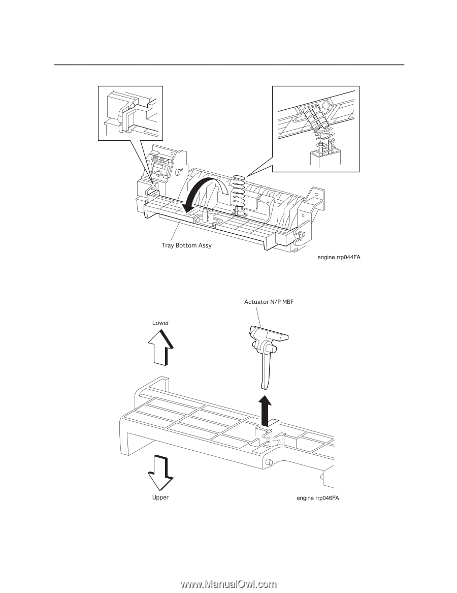
| RRP 4.1.4 Tray Bottom Assy (PL4.1.8) |
238 |
| RRP 4.1.4 Tray Bottom Assy (PL4.1.8) continued |
239 |
| 1. Remove the Cover Assy Front (RRP 1.1.8). |
239 |
| 2. Remove the Cover Front L/H (RRP 1.1.10). |
239 |
| 3. Remove the Chute MBF Assy (RRP 4.1.1). |
239 |
| 4. Remove the Spring MBF (RRP 4.1.9). |
239 |
| 5. Remove the Gear Pick Up (RRP 4.1.10). |
239 |
| 6. Remove the Roll Assy MBF (with3-6,28)(RRP 4.1.2). |
239 |
| 7. Disengaging two hooks that secure the Tray Bottom Assy to the Chute MBF Assy, open the Tray Bo... |
239 |
| 8. Remove the Tray Bottom Pick Up. (RRP 4.1.12) |
239 |
| 9. Unhook the right Bearing Exit (PL4.1.14) secured to the Tray Bottom Assy from the Chute MBF Assy. |
239 |
| 10. Unhook the left Bearing Exit secured to the Tray Bottom Assy from the Chute MBF Assy. |
239 |
| 11. Remove the Tray Bottom Assy together with the left and right Bearing Exits from the Chute MBF... |
239 |
| 12. Remove the Bearing Exits from the left and right shafts of Tray Bottom Assy. |
239 |
| 1. Mount the Bearing Exits on the left and right shafts of Tray Bottom Assy. |
239 |
| 2. Aligning the position exactly, mount the Tray Bottom Assy together with the left and right Bea... |
239 |
| 3. Secure the left shaft of Tray Bottom Assy to the Chute MBF Assy with a hook of Bearing Exit. |
239 |
| 4. Secure the right shaft of Tray Bottom Assy to the Chute MBF Assy with a hook of Bearing Exit. |
239 |
| 5. Mount the Tray Bottom Pick Up (RRP 4.1.12). |
239 |
| 6. Insert the Spring Tray Bottom MBF (PL4.1.13) into two studs of Tray Bottom Pick Up from the Ch... |
239 |
| 7. Deflecting the right hook of Chute MBF Assy, rotate the Tray Bottom Assy together with the Tra... |
239 |
| 8. Insert two shafts of Chute MBF Assy into two stud holes of Tray Bottom Pick Up to secure the T... |
239 |
| 9. Mount the Roll Assy MBF (with3-6,28)(RRP 4.1.2). |
239 |
| 10. Mount the Gear Pick Up (RRP 4.1.10). |
239 |
| 11. Mount the Spring MBF (RRP 4.1.9). |
239 |
| 12. Mount the Chute MBF Assy (RRP 4.1.1). |
239 |
| 13. Mount the Cover Front L/H (RRP 1.1.10). |
239 |
| 14. Mount the Cover Assy Front (RRP 1.1.8). |
239 |
| RRP 4.1.5 Actuator N/P MBF(PL4.1.12) |
240 |
| RRP 4.1.5 Actuator N/P MBF(PL4.1.12) continued |
241 |
| 1. Remove the Cover Assy Front (RRP 1.1.8). |
241 |
| 2. Remove the Cover Front L/H (RRP 1.1.10). |
241 |
| 3. Remove the Chute MBF Assy (RRP 4.1.1). |
241 |
| 4. Remove the Spring MBF (RRP 4.1.9). |
241 |
| 5. Remove the Gear Pick Up (RRP 4.1.10). |
241 |
| 6. Remove the Roll Assy MBF (with3-6,28)(RRP 4.1.2). |
241 |
| 7. Disengaging two hooks that secure the Tray Bottom Assy to the Chute MBF Assy (PL4.1.1), open t... |
241 |
| 8. Remove the Tray Bottom Pick Up (RRP 4.1.12). |
241 |
| 9. Disengaging two hooks that secure the Actuator N/P MBF to the back of Tray Bottom (PL4.1.11), ... |
241 |
| 1. Aligning the position exactly, mount the Actuator N/P MBF on the back of Tray Bottom (PL4.1.11... |
241 |
| 2. Secure the shaft of Actuator N/P MBF to two hooks on the back of Tray Bottom. |
241 |
| 3. Mount the Tray Bottom Pick Up (RRP 4.1.12). |
241 |
| 4. Insert the Spring Tray Bottom MBF (PL4.1.13) into two studs of Tray Bottom Pick Up from the Ch... |
241 |
| 5. Deflecting the right hook of Chute MBF Assy, rotate the Tray Bottom Assy together with the Tra... |
241 |
| 6. Insert two shafts of Chute MBF Assy into two stud holes of Tray Bottom Pick Up to secure the T... |
241 |
| 7. Mount the Roll Assy MBF (with3-6,28)(RRP 4.1.2). |
241 |
| 8. Mount the Gear Pick Up (RRP 4.1.10). |
241 |
| 9. Mount the Spring MBF (RRP 4.1.9). |
241 |
| 10. Mount the Chute MBF Assy (RRP 4.1.1). |
241 |
| 11. Mount the Cover Front L/H (RRP 1.1.10). |
241 |
| 12. Mount the Cover Assy Front (RRP 1.1.8). |
241 |
| RRP 4.1.6 Pad Assy Retard (PL4.1.15) |
242 |
| RRP 4.1.6 Pad Assy Retard (PL4.1.15) continued |
243 |
| 1. Remove the Cover Assy Front (RRP 1.1.8). |
243 |
| 2. Remove the Cover Front L/H (RRP 1.1.10). |
243 |
| 3. Remove the Chute MBF Assy (RRP 4.1.1). |
243 |
| 4. Remove the Spring MBF (RRP 4.1.9). |
243 |
| 5. Remove the Gear Pick Up (RRP 4.1.10). |
243 |
| 6. Remove the Roll Assy MBF (with3-6,28)(RRP 4.1.2). |
243 |
| 7. Disengaging two hooks that secure the Tray Bottom Assy to the Chute MBF Assy (PL4.1.1), open t... |
243 |
| 8. Remove the Tray Bottom Pick Up (RRP 4.1.12). |
243 |
| 9. Deflecting the left bracket of Pad Assy Retard from the Chute MBF Assy, disengage the hole in ... |
243 |
| 10. Deflecting the right bracket of Pad Assy Retard from the Chute MBF Assy, disengage the hole i... |
243 |
| 1. Engage the hole in the right bracket of Pad Assy Retard with the right boss of Chute MBF Assy ... |
243 |
| 2. Deflecting the left bracket of Pad Assy Retard, engage the left boss of Chute MBF Assy with th... |
243 |
| 3. Mount the Tray Bottom Pick Up (RRP 4.1.11). |
243 |
| 4. Insert the Spring Tray Bottom MBF (PL4.1.13) into two studs of Tray Bottom Pick Up from the Ch... |
243 |
| 5. Deflecting the right hook of Chute MBF Assy, rotate the Tray Bottom Assy together with the Tra... |
243 |
| 6. Insert two shafts of Chute MBF Assy into two stud holes of Tray Bottom Pick Up to secure the T... |
243 |
| 7. Mount the Roll Assy MBF (with3-6,28)(RRP 4.1.2). |
243 |
| 8. Mount the Gear Pick Up (RRP 4.1.10). |
243 |
| 9. Mount the Spring MBF (RRP 4.1.9). |
243 |
| 10. Mount the Chute MBF Assy (RRP 4.1.1). |
243 |
| 11. Mount the Cover Front L/H (RRP 1.1.10). |
243 |
| 12. Mount the Cover Assy Front (RRP 1.1.8). |
243 |
| RRP 4.1.7 Sensor Photo:Paper Set (PL4.1.19) |
244 |
| RRP 4.1.7 Sensor Photo:Paper Set (PL4.1.19) continued |
245 |
| 1. Remove the Cover Assy Front (RRP 1.1.8). |
245 |
| 2. Remove the Cover Front L/H (RRP 1.1.10). |
245 |
| 3. Remove the Chute MBF Assy (RRP 4.1.1). |
245 |
| 4. Remove the Spring MBF (RRP 4.1.9). |
245 |
| 5. Remove the Gear Pick Up (RRP 4.1.10). |
245 |
| 6. Remove the Roll Assy MBF (with3-6,28)(RRP 4.1.2). |
245 |
| 7. Disengaging two hooks that secure the Tray Bottom Assy to the Chute MBF Assy (PL4.1.1), open t... |
245 |
| 8. Remove the Tray Bottom Pick Up (RRP 4.1.12). |
245 |
| 9. Draw off the Spring Tray Bottom MBF (PL4.1.13) from two studs in the Chute MBF Assy. |
245 |
| 10. Unplug the connector (P/J451) from the Sensor Photo: Paper Set. |
245 |
| 11. Disengage five hooks of Sensor Photo: Paper Set, and remove the Sensor Photo:Paper Set from t... |
245 |
| 1. Aligning the position exactly, secure the Sensor Photo: Paper Set to the Chute Assy MBF with f... |
245 |
| 2. Plug the connector (P/J451) to the Sensor Photo: Paper Set. |
245 |
| 3. Insert the Spring Tray Bottom MBF (PL4.1.13) into two studs of Chute MBF Assy. |
245 |
| 4. Mount the Tray Bottom Pick Up. (RRP 4.1.12) |
245 |
| 5. Insert the Spring Tray Bottom MBF (PL4.1.13) into two studs of Tray Bottom Pick Up from the Ch... |
245 |
| 6. Deflecting the right hook of Chute MBF Assy, rotate the Tray Bottom Assy together with the Tra... |
245 |
| 7. Insert two shafts of Chute MBF Assy into two stud holes of Tray Bottom Pick Up to secure the T... |
245 |
| 8. Mount the Roll Assy MBF (with3-6,28)(RRP 4.1.2). |
245 |
| 9. Mount the Gear Pick Up (RRP 4.1.10). |
245 |
| 10. Mount the Spring MBF (RRP 4.1.9). |
245 |
| 11. Mount the Chute MBF Assy (RRP 4.1.1). |
245 |
| 12. Mount the Cover Front L/H (RRP 1.1.10). |
245 |
| 13. Mount the Cover Assy Front (RRP 1.1.8). |
245 |
| RRP 4.1.8 Solenoid Pick Up (PL4.1.23) |
246 |
| RRP 4.1.8 Solenoid Pick Up (PL4.1.23) continued |
247 |
| 1. Remove the Cover Assy Front (RRP 1.1.8). |
247 |
| 2. Remove the Cover Front L/H (RRP 1.1.10). |
247 |
| 3. Remove the Chute MBF Assy (RRP 4.1.1). |
247 |
| 4. Remove the Spring MBF (RRP 4.1.9). |
247 |
| 5. Remove the Gear Pick Up (RRP 4.1.10). |
247 |
| 6. Remove the one screw securing the Solenoid Pick Up to the Chute MBF Assy. |
247 |
| 7. Remove the Solenoid Pick Up from the Chute MBF Assy. |
247 |
| 1. Align the Solenoid Pick Up with its mount position to the Chute MBF Assy. |
247 |
| 2. Secure the Solenoid Pick Up to the Chute MBF Assy with one screw. |
247 |
| 3. Mount the Gear Pick Up (RRP 4.1.10). |
247 |
| 4. Mount the Spring MBF (RRP 4.1.9). |
247 |
| 5. Mount the Chute MBF Assy (RRP 4.1.1). |
247 |
| 6. Mount the Cover Front L/H (RRP 1.1.10). |
247 |
| 7. Mount the Cover Assy Front (RRP 1.1.8). |
247 |
| RRP 4.1.9 Spring MBF (PL4.1.24) |
248 |
| RRP 4.1.9 Spring MBF (PL4.1.24) continued |
249 |
| 1. Remove the Cover Assy Front (RRP 1.1.8). |
249 |
| 2. Remove the Cover Front L/H (RRP 1.1.10). |
249 |
| 3. Remove the Chute MBF Assy (RRP 4.1.1). |
249 |
| 4. Unhook the Spring MBF secured to the Gear Pick Up (PL4.1.25) from the Chute MBF Assy (PL4.1.1). |
249 |
| 5. Unhook the Spring MBF secured to the hole in the Chute MBF Assy, and remove the Spring MBF. |
249 |
| 1. Hook the Spring MBF to the boss of Gear Pick Up of Chute MBF Assy. |
249 |
| 2. Hook the Spring MBF to the hole in Chute MBF Assy. |
249 |
| 3. Mount the Chute MBF Assy (RRP 4.1.1). |
249 |
| 4. Mount the Cover Front L/H (RRP 1.1.10). |
249 |
| 5. Mount the Cover Assy Front (RRP 1.1.8). |
249 |
| RRP 4.1.10 Gear Pick Up (PL4.1.25) |
250 |
| RRP 4.1.10 Gear Pick Up (PL4.1.25) continued |
251 |
| 1. Remove the Cover Assy Front (RRP 1.1.8). |
251 |
| 2. Remove the Cover Front L/H (RRP 1.1.10). |
251 |
| 3. Remove the Chute MBF Assy (RRP 4.1.1). |
251 |
| 4. Remove the Spring MBF (RRP 4.1.9). |
251 |
| 5. Unhook the Gear Pick Up secured to the Shaft Assy MBF (PL4.1.3) from the Chute MBF Assy (PL4.1... |
251 |
| 6. Draw the Gear Pick Up from the Shaft Assy MBF. |
251 |
| 1. Insert the Gear Pick Up into the left shaft of Shaft Assy MBF (PL4.1.3) from the Chute MBF Ass... |
251 |
| 2. Hook the Gear Pick Up to the groove in the shaft of Shaft Assy MBF (PL4.1.3). |
251 |
| 3. Mount the Spring MBF (RRP 4.1.9). |
251 |
| 4. Mount the Chute MBF Assy (RRP 4.1.1). |
251 |
| 5. Mount the Cover Front L/H (RRP 1.1.10). |
251 |
| 6. Mount the Cover Assy Front (RRP 1.1.8). |
251 |
| RRP 4.1.11 Connector Assy ENV. (PL4.1.27) |
252 |
| RRP 4.1.11 Connector Assy ENV (PL4.1.27) continued |
253 |
| 1. Remove the Cover Assy Front (RRP 1.1.8). |
253 |
| 2. Remove the Cover Front L/H (RRP 1.1.10). |
253 |
| 3. Remove the Chute MBF Assy (RRP 4.1.1). |
253 |
| 4. Sliding the Plate ENV Assy (PL4.1.30) toward the left, remove it from the Chute Assy MBF (PL4.... |
253 |
| 5. Remove the one screw securing the Connector Assy ENV to the Plate ENV Assy. |
253 |
| 6. Remove the Connector Assy ENV from the Plate ENV Assy. |
253 |
| 1. Align the Connector Assy ENV with its mount position to the Plate ENV Assy (PL4.1.30). |
253 |
| 2. Secure the Connector Assy ENV to the Plate ENV Assy with one screw. |
253 |
| 3. Sliding the Plate ENV Assy toward the right, mount it to the Chute Assy MBF (PL4.1.1). |
253 |
| 4. Mount the Chute MBF Assy (RRP 4.1.1). |
253 |
| 5. Mount the Cover Front L/H (RRP 1.1.10). |
253 |
| 6. Mount the Cover Assy Front (RRP 1.1.8). |
253 |
| RRP 4.1.12 Tray Bottom Pick Up (with9,10) (Reference Only) |
254 |
| RRP 4.1.12 Tray Bottom Pick Up (with9,10) (Reference Only) continued |
255 |
| 1. Remove the Cover Assy Front (RRP 1.1.8). |
255 |
| 2. Remove the Cover Front L/H (RRP 1.1.10). |
255 |
| 3. Remove the Chute MBF Assy (RRP 4.1.1). |
255 |
| 4. Remove the Spring MBF (RRP 4.1.9). |
255 |
| 5. Remove the Gear Pick Up (RRP 4.1.10). |
255 |
| 6. Remove the Roll Assy MBF (with3-6,28)(RRP 4.1.2). |
255 |
| 7. Disengaging two hooks that secure the Tray Bottom Assy (PL4.1.14) to the Chute MBF Assy (PL4.1... |
255 |
| 8. Rotate the Tray Bottom Pick Up by about 90 degrees toward the front from the Tray Bottom Assy. |
255 |
| 9. Remove the Tray Bottom Pick Up from the shaft of Tray Bottom Assy. |
255 |
| 1. Aligning the position exactly, mount the Tray Bottom Pick Up on the shaft of Tray Bottom Assy ... |
255 |
| 2. Rotate the Tray Bottom Pick Up by about 90 degrees toward the rear from the Tray Bottom Assy. |
255 |
| 3. Insert the Spring Tray Bottom MBF (PL4.1.13) into two studs of Tray Bottom Pick Up from the Ch... |
255 |
| 4. Deflecting the right hook of Chute MBF Assy, rotate the Tray Bottom Assy together with the Tra... |
255 |
| 5. Insert two shafts of Chute MBF Assy into two stud holes of Tray Bottom Pick Up to secure the T... |
255 |
| 6. Mount the Roll Assy MBF (with3-6,28)(RRP 4.1.2). |
255 |
| 7. Mount the Gear Pick Up (RRP 4.1.10). |
255 |
| 8. Mount the Spring MBF (RRP 4.1.9). |
255 |
| 9. Mount the Chute MBF Assy (RRP 4.1.1). |
255 |
| 10. Mount the Cover Front L/H (RRP 1.1.10). |
255 |
| 11. Mount the Cover Assy Front (RRP 1.1.8). |
255 |
| RRP 5.1.1 P/H Assy (PL5.1.4) |
256 |
| RRP 5.1.1 P/H Assy (PL5.1.4) continued |
257 |
| 1. Remove the Cover Assy Front (RRP 1.1.8). |
257 |
| 2. Remove the Cover Front L/H (RRP 1.1.10). |
257 |
| 3. Remove the Chute MBF Assy (RRP 4.1.1). |
257 |
| 4. Remove the Shaft 14 (RRP 5.1.10). |
257 |
| 5. Remove the Gear 14 (RRP 5.1.10). |
257 |
| 6. Unplug the connector (P/J42) in the P/H Assy. |
257 |
| 7. Unplug the connector (P/J43) in the P/H Assy. |
257 |
| 8. Release two clamps on the harness of P/H Assy. |
257 |
| 9. Remove the five screws securing the P/H Assy to the printer. |
257 |
| 10. Raising a little the right end of P/H Assy to shift to the right, remove the P/H Assy upward ... |
257 |
| 1. Insert the P/H Assy from diagonal right into the printer, and align the position. |
257 |
| 2. Secure the P/H Assy to the printer with five screws. |
257 |
| 3. Secure the harness of P/H Assy with two clamps. |
257 |
| 4. Plug the connector (P/J42) in the P/H Assy. |
257 |
| 5. Plug the connector (P/J43) in the P/H Assy. |
257 |
| 6. Mount the Gear 14 (RRP 5.1.10). |
257 |
| 7. Mount the Shaft 14 (RRP 5.1.10). |
257 |
| 8. Mount the Chute MBF Assy (RRP 4.1.1). |
257 |
| 9. Mount the Cover Front L/H (RRP 1.1.10). |
257 |
| 10. Mount the Cover Assy Front (RRP 1.1.8). |
257 |
| RRP 5.1.2 Roll Regi Rubber (PL5.1.7) |
258 |
| RRP 5.1.2 Roll Regi Rubber (PL5.1.7) continued |
259 |
| 1. Remove the Cover Assy Front (RRP 1.1.8). |
259 |
| 2. Remove the Cover Front L/H (RRP 1.1.10). |
259 |
| 3. Remove the Chute MBF Assy (RRP 4.1.1). |
259 |
| 4. Remove the Shaft 14 (RRP 5.1.10). |
259 |
| 5. Remove the Gear 14 (RRP 5.1.10). |
259 |
| 6. Remove the P/H Assy (RRP 5.1.1). |
259 |
| 7. Remove the Spring Regi L (RRP 5.1.6). |
259 |
| 8. Remove the Gear Regi Metal (RRP 5.1.7). |
259 |
| 9. Remove the Gear Regi Rubber (RRP 5.1.8). |
259 |
| 10. Remove the Clutch Regi (RRP 5.1.9). |
259 |
| 11. Disengage the left E-ring that secures the Roll Regi Metal (PL5.1.5) to the P/H Assy (PL5.1.1). |
259 |
| 12. Unhook the Spring Torsion (PL5.1.29) from the notch of Chute Upper Assy (PL5.1.6). |
259 |
| 13. Move the Spring Torsion to the left from the P/H Assy, avoiding the boss of Bearing Metal R (... |
259 |
| 14. Closing the Chute Upper Assy and Chute Inlet (PL5.1.8), align the boss of Bearing Metal R wit... |
259 |
| 15. Closing the Chute Upper Assy and Chute Inlet, align the boss of Bearing Metal (PL5.1.13) with... |
259 |
| 16. Draw upward the right shaft of Roll Regi Metal from the right bearing of P/H Assy. |
259 |
| 17. Draw diagonal rightward the Roll Regi Metal together with Chute Upper Assy and Chute Inlet fr... |
259 |
| 18. Remove the Bearing Rubber R (PL5.1.17) that secures the Roll Regi Rubber to the P/H Assy. |
259 |
| 19. Remove the Bearing Rubber L (PL5.1.18) that secures the Roll Regi Rubber to the P/H Assy. |
259 |
| 20. Moving the Roll Regi Rubber to the right from the P/H Assy, draw the left shaft of Roll Regi ... |
259 |
| 21. Draw upward the right shaft of Roll Regi Rubber from the bearing of P/H Assy, and draw diagon... |
259 |
| RRP 5.1.2 Roll Regi Rubber (PL5.1.7) continued |
260 |
| 1. Insert the left shaft of Roll Regi Rubber into the left bearing bore of P/H Assy (PL5.1.1). |
260 |
| 2. Insert the right shaft of Roll Regi Rubber into the right bearing of P/H Assy. |
260 |
| 3. Insert the right shaft of Roll Regi Rubber into the left bearing bore of P/H Assy. |
260 |
| 4. Secure the Roll Regi Rubber to the P/H Assy with the Bearing Rubber L (PL5.1.18). |
260 |
| 5. Secure the Roll Regi Rubber to the P/H Assy with the Bearing Rubber R (PL5.1.17). |
260 |
| 6. Insert the right shaft of Roll Regi Metal (PL5.1.5) together with Chute Upper Assy (PL5.1.6) a... |
260 |
| 7. Insert the right shaft of Roll Regi Metal into the right bearing of P/H Assy. |
260 |
| 8. Closing the Chute Upper Assy and Chute Inlet from the P/H Assy, engage the boss of Bearing Met... |
260 |
| 9. Closing the Chute Upper Assy and Chute Inlet from the P/H Assy, engage the boss of Bearing Met... |
260 |
| 10. Moving the Spring Torsion (PL5.1.29) to the right from P/H Assy, insert it into the Bearing M... |
260 |
| 11. From the P/H Assy, hook the Spring Torsion to the notch of Chute Upper Assy. |
260 |
| 12. Secure the left shaft of Roll Regi Metal to the P/H Assy with the E-ring. |
260 |
| 13. Mount the Clutch Regi (RRP 5.1.9). |
260 |
| 14. Mount the Gear Regi Rubber (RRP 5.1.8). |
260 |
| 15. Mount the Gear Regi Metal (RRP 5.1.7). |
260 |
| 16. Mount the Spring Regi L (RRP 5.1.6). |
260 |
| 17. Mount the P/H Assy (RRP 5.1.1.). |
260 |
| 18. Mount the Gear 14 (RRP 5.1.10). |
260 |
| 19. Mount the Shaft 14 (RRP 5.1.10). |
260 |
| 20. Mount the Chute MBF Assy (RRP 4.1.1). |
260 |
| 21. Mount the Cover Front L/H (RRP 1.1.10). |
260 |
| 22. Mount the Cover Assy Front (RRP 1.1.8). |
260 |
| RRP 5.1.2 Roll Regi Rubber (PL5.1.7) continued |
261 |
| RRP 5.1.3 Actuator Regi (PL5.1.10) |
262 |
| RRP 5.1.3 Actuator Regi (PL5.1.10) continued |
263 |
| 1. Remove the Cover Assy Front (RRP 1.1.8). |
263 |
| 2. Remove the Cover Front L/H (RRP 1.1.10). |
263 |
| 3. Remove the Chute MBF Assy (RRP 4.1.1). |
263 |
| 4. Remove the Shaft 14 (RRP 5.1.10). |
263 |
| 5. Remove the Gear 14 (RRP 5.1.10). |
263 |
| 6. Remove the P/H Assy (RRP 5.1.1). |
263 |
| 7. Open upward the Chute Upper (PL5.1.6) together with Holder Toner Sensor (PL5.1.2) from the P/H... |
263 |
| 8. Disengage the right hook of Spring Sensor Regi (PL5.1.11) from the P/H Assy. |
263 |
| 9. Holding the operating lever of Actuator Regi, move it to the left to remove the right shaft of... |
263 |
| 10. Remove the Spring Sensor Regi inserted in the shaft of Actuator Regi. |
263 |
| 1. Insert the Spring Sensor Regi (PL5.1.11) into the right shaft of Actuator Regi. |
263 |
| 2. Holding the operating lever of Actuator Regi, insert the left shaft into the left hole in the ... |
263 |
| 3. Holding the operating lever of Actuator Regi, push the bracket of P/H Assy with the left shaft... |
263 |
| 4. Engage the left hook of Spring Sensor Regi with the back of operating lever of Actuator Regi, ... |
263 |
| 5. Close downward the Chute Upper (PL5.1.6) together with Holder Toner Sensor (PL5.1.2) from the ... |
263 |
| 6. Mount the P/H Assy (RRP 5.1.1). |
263 |
| 7. Mount the Gear 14 (RRP 5.1.10). |
263 |
| 8. Mount the Shaft 14 (RRP 5.1.10). |
263 |
| 9. Mount the Chute MBF Assy (RRP 4.1.1). |
263 |
| 10. Mount the Cover Front L/H (RRP 1.1.10). |
263 |
| 11. Mount the Cover Assy Front (RRP 1.1.8). |
263 |
| RRP 5.1.4 Spring Sensor Regi (PL5.1.11) |
264 |
| RRP 5.1.4 Spring Sensor Regi (PL5.1.11) continued |
265 |
| 1. Remove the Cover Assy Front (RRP 1.1.8). |
265 |
| 2. Remove the Cover Front L/H (RRP 1.1.10). |
265 |
| 3. Remove the Chute MBF Assy (RRP 4.1.1). |
265 |
| 4. Remove the Shaft 14 (RRP 5.1.10). |
265 |
| 5. Remove the Gear 14 (RRP 5.1.10). |
265 |
| 6. Remove the P/H Assy (RRP 5.1.1). |
265 |
| 7. Open upward the Chute Upper (PL5.1.6) together with Holder Toner Sensor (PL5.1.2) from the P/H... |
265 |
| 8. Disengage the right hook of Spring Sensor Regi from the P/H Assy. |
265 |
| 9. Holding the operating lever of Actuator Regi, move it to the left to remove the right shaft of... |
265 |
| 10. Remove the Spring Sensor Regi inserted in the shaft of Actuator Regi. |
265 |
| 1. Insert the Spring Sensor Regi into the right shaft of Actuator Regi (PL5.1.10). |
265 |
| 2. Holding the operating lever of Actuator Regi, insert the left shaft into the left hole in the ... |
265 |
| 3. Holding the operating lever of Actuator Regi, push the bracket of P/H Assy with the left shaft... |
265 |
| 4. Engage the left hook of Spring Sensor Regi with the back of operating lever of Actuator Regi, ... |
265 |
| 5. Close downward the Chute Upper (PL5.1.6) together with Holder Toner Sensor (PL5.1.2) from the ... |
265 |
| 6. Mount the P/H Assy (RRP 5.1.1). |
265 |
| 7. Mount the Gear 14 (RRP 5.1.10). |
265 |
| 8. Mount the Shaft 14 (RRP 5.1.10). |
265 |
| 9. Mount the Chute MBF Assy (RRP 4.1.1). |
265 |
| 10. Mount the Cover Front L/H (RRP 1.1.10). |
265 |
| 11. Mount the Cover Assy Front (RRP 1.1.8). |
265 |
| RRP 5.1.5 Sensor Photo:Regi (PL5.1.12) |
266 |
| RRP 5.1.5 Sensor Photo:Regi (PL5.1.12) continued |
267 |
| 1. Remove the Cover Assy Front (RRP 1.1.8). |
267 |
| 2. Remove the Cover Front L/H (RRP 1.1.10). |
267 |
| 3. Remove the Chute MBF Assy (RRP 4.1.1). |
267 |
| 4. Remove the Shaft 14 (RRP 5.1.10). |
267 |
| 5. Remove the Gear 14 (RRP 5.1.10). |
267 |
| 6. Remove the P/H Assy (RRP 5.1.1). |
267 |
| 7. Open upward the Chute Upper (PL5.1.6) together with Holder Toner Sensor (PL5.1.2) from the P/H... |
267 |
| 8. Remove the Actuator Regi (RRP 5.1.4) |
267 |
| 9. Unplug the connector (P/J432) from the Sensor Photo. |
267 |
| 10. Disengage three hooks that secure the Sensor Photo, and remove the Sensor Photo from the rear... |
267 |
| 1. Aligning the position exactly, secure the Sensor Photo to the P/H Assy (PL5.1.4) with three ho... |
267 |
| 2. plug the connector (P/J432) in the Sensor Photo. |
267 |
| 3. Mount the Actuator Regi (RRP 5.1.4). |
267 |
| 4. Close down-ward the Chute Upper (PL5.1.6) together with Holder Toner Sensor (PL5.1.2) from the... |
267 |
| 5. Mount the P/H Assy (RRP 5.1.1) |
267 |
| 6. Mount the Gear 14 (RRP 5.1.10). |
267 |
| 7. Mount the Shaft 14 (RRP 5.1.10). |
267 |
| 8. Mount the Chute MBF Assy (RRP 4.1.1). |
267 |
| 9. Mount the Cover Front L/H (RRP 1.1.10). |
267 |
| 10. Mount the Cover Assy Front (RRP 1.1.8). |
267 |
| RRP 5.1.6 Spring Regi L (PL5.1.14) |
268 |
| RRP 5.1.6 Spring Regi L (PL5.1.14) continued |
269 |
| 1. Remove the Cover Assy Front (RRP 1.1.8). |
269 |
| 2. Remove the Cover Front L/H (RRP 1.1.10). |
269 |
| 3. Remove the Chute MBF Assy (RRP 4.1.1). |
269 |
| 4. Remove the Shaft 14 (RRP 5.1.10). |
269 |
| 5. Remove the Gear 14 (RRP 5.1.10). |
269 |
| 6. Remove the P/H Assy (RRP 5.1.1). |
269 |
| 7. Using a small screwdriver, unhook the right Spring Regi L secured to the Bearing Metal R (PL5.... |
269 |
| 8. Using a small screwdriver, unhook the right Spring Regi L secured to the Chute Bottom Upper (P... |
269 |
| 9. Using a small screwdriver, unhook the left Spring Regi L secured to the Bearing Metal L (PL5.1... |
269 |
| 10. Using a small screwdriver, unhook the left Spring Regi L secured to the Chute Bottom Upper. |
269 |
| 11. Draw downward the right Spring Regi L from the P/H Assy (PL5.1.4). |
269 |
| 12. Draw downward the left Spring Regi L from the P/H Assy. |
269 |
| 1. From the left side of P/H Assy (PL5.1.4), pass the hook at the top of Spring Regi L through a ... |
269 |
| 2. From the P/H Assy, engage the hook at the top of left Spring Regi L with the Bearing Metal L (... |
269 |
| 3. From the P/H Assy, engage the hook at the bottom of left Spring Regi L with the Screw Earth (P... |
269 |
| 4. From the right side of P/H Assy, pass the hook at the top of Spring Regi L through a section b... |
269 |
| 5. From the P/H Assy, engage the hook at the top of right Spring Regi L with the Bearing Metal R ... |
269 |
| 6. From the P/H Assy, engage the hook at the bottom of right Spring Regi L with the Screw Earth. |
269 |
| 7. Mount the P/H Assy (RRP 5.1.1). |
269 |
| 8. Mount the Gear 14 (RRP 5.1.10). |
269 |
| 9. Mount the Shaft 14 (RRP 5.1.10). |
269 |
| 10. Mount the Chute MBF Assy (RRP 4.1.1). |
269 |
| 11. Mount the Cover Front L/H (RRP 1.1.10). |
269 |
| 12. Mount the Cover Assy Front (RRP 1.1.8). |
269 |
| RRP 5.1.7 Gear Regi Metal(PL5.1.15) |
270 |
| RRP 5.1.7 Gear Regi Metal(PL5.1.15) continued |
271 |
| 1. Remove the Cover Assy Front (RRP 1.1.8). |
271 |
| 2. Remove the Cover Front L/H (RRP 1.1.10). |
271 |
| 3. Remove the Chute MBF Assy (RRP 4.1.1). |
271 |
| 4. Remove the Shaft 14 (RRP 5.1.10). |
271 |
| 5. Remove the Gear 14 (RRP 5.1.10). |
271 |
| 6. Remove the P/H Assy (RRP 5.1.1). |
271 |
| 7. Disengage the E-ring that secures the Gear Regi Metal from the P/H Assy (PL5.1.4). |
271 |
| 8. Draw the Gear Regi Metal from the P/H Assy. |
271 |
| 1. Mount the Gear Regi Metal on the Roll Regi Metal (PL5.1.5) from the P/H Assy (PL5.1.4). |
271 |
| 2. Secure the Gear Regi Metal to the Roll Regi Metal of P/H Assy with the E-ring. |
271 |
| 3. Mount the P/H Assy (RRP 5.1.1). |
271 |
| 4. Mount the Gear 14 (RRP 5.1.10). |
271 |
| 5. Mount the Shaft 14 (RRP 5.1.10). |
271 |
| 6. Mount the Chute MBF Assy (RRP 4.1.1). |
271 |
| 7. Mount the Cover Front L/H (RRP 1.1.10). |
271 |
| 8. Mount the Cover Assy Front (RRP 1.1.8). |
271 |
| RRP 5.1.8 Gear Regi Rubber (PL5.1.16) |
272 |
| RRP 5.1.8 Gear Regi Rubber (PL5.1.16) continued |
273 |
| 1. Remove the Cover Assy Front (RRP 1.1.8). |
273 |
| 2. Remove the Cover Front L/H (RRP 1.1.10). |
273 |
| 3. Remove the Chute MBF Assy (RRP 4.1.1). |
273 |
| 4. Remove the Shaft 14 (RRP 5.1.10). |
273 |
| 5. Remove the Gear 14 (RRP 5.1.10). |
273 |
| 6. Remove the P/H Assy (RRP 5.1.1). |
273 |
| 7. Disengage the E-ring that secures the Gear Regi Rubber from the P/H Assy (PL5.1.4). |
273 |
| 8. Draw the Gear Regi Rubber from the P/H Assy. |
273 |
| 1. Mount the Gear Regi Rubber on the Roll Regi Rubber (PL5.1.7) of the P/H Assy (PL5.1.4). |
273 |
| 2. Secure the Gear Regi Rubber to the Roll Regi Rubber from P/H Assy with the E-ring. |
273 |
| 3. Mount the P/H Assy (RRP 5.1.1). |
273 |
| 4. Mount the Gear 14 (RRP 5.1.10). |
273 |
| 5. Mount the Shaft 14 (RRP 5.1.10). |
273 |
| 6. Mount the Chute MBF Assy (RRP 4.1.1). |
273 |
| 7. Mount the Cover Front L/H (RRP 1.1.10). |
273 |
| 8. Mount the Cover Assy Front (RRP 1.1.8). |
273 |
| RRP 5.1.9 Clutch Regi (PL5.1.19) |
274 |
| RRP 5.1.9 Clutch Regi (PL5.1.19) continued |
275 |
| 1. Remove the Cover Assy Front (RRP 1.1.8). |
275 |
| 2. Remove the Cover Front L/H (RRP 1.1.10). |
275 |
| 3. Remove the Chute MBF Assy (RRP 4.1.1). |
275 |
| 4. Remove the Shaft 14 (RRP 5.1.10). |
275 |
| 5. Remove the Gear 14 (RRP 5.1.10). |
275 |
| 6. Remove the P/H Assy (RRP 5.1.1). |
275 |
| 7. Unplug the connector (P/J433) of the Clutch Regi. |
275 |
| 8. Disengage the E-ring that secures the Clutch Regi from the P/H Assy (PL5.1.4). |
275 |
| 9. Draw the Clutch Regi from the P/H Assy. |
275 |
| 1. Mount the Clutch Regi on the Roll Regi Rubber (PL5.1.7) of the P/H Assy (PL5.1.4). |
275 |
| 2. Secure the Cluch Regi to the Roll Regi Rubber from P/H Assy with the E-ring. |
275 |
| 3. plug the connector (P/J433) in the Clutch Regi. |
275 |
| 4. Mount the P/H Assy (RRP 5.1.1). |
275 |
| 5. Mount the Gear 14 (RRP 5.1.10). |
275 |
| 6. Mount the Shaft 14 (RRP 5.1.10). |
275 |
| 7. Mount the Chute MBF Assy (RRP 4.1.1). |
275 |
| 8. Mount the Cover Front L/H (RRP 1.1.10). |
275 |
| 9. Mount the Cover Assy Front (RRP 1.1.8). |
275 |
| RRP 5.1.10 Shaft 14 (PL5.1.34) and Gear 14 (PL5.1.35) |
276 |
| RRP 5.1.10 Shaft 14 (PL5.1.34) and Gear 14 (PL5.1.35) continued |
277 |
| 1. Remove the Cover Assy Front (RRP 1.1.8). |
277 |
| 2. Remove the Cover Front L/H (RRP 1.1.10). |
277 |
| 3. Remove the Chute MBF Assy (RRP 4.1.1). |
277 |
| 4. Holding the Gear 14, draw off the Shaft 14 that secures the P/H Assy (PL5.1.4) from the printe... |
277 |
| 5. Remove the Gear 14 from the printer. |
277 |
| 1. Align the the Gear 14 with its mount position to the printer. |
277 |
| 2. Insert the Shaft 14 from the hole in the P/H Assy (PL5.1.4), and secure the Gear 14 to the pri... |
277 |
| 3. Mount the Chute MBF Assy (RRP 4.1.1). |
277 |
| 4. Mount the Cover Front L/H (RRP 1.1.10). |
277 |
| 5. Mount the Cover Assy Front (RRP 1.1.8). |
277 |
| RRP 5.1.11 Kit Toner Sensor (with 1,2,33)(Reference Only) |
278 |
| RRP 5.1.11 Kit Toner Sensor (with 1,2,33)(Reference Only) continued |
279 |
| 1. Remove the Cover Assy Front (RRP 1.1.8). |
279 |
| 2. Remove the Cover Front L/H (RRP 1.1.10). |
279 |
| 3. Remove the Chute MBF Assy (RRP 4.1.1). |
279 |
| 4. Remove the Shaft 14 (RRP 5.1.10). |
279 |
| 5. Remove the Gear 14 (RRP 5.1.10). |
279 |
| 6. Remove the P/H Assy (RRP 5.1.1). |
279 |
| 7. Unplug the connector (P/J421)on the Kit Toner Sensor from the P-H Assy(PL5.1.4). |
279 |
| 8. Deflecting the left bracket of Kit Toner Sensor, from the P/H Assy (PL5.1.4), desengage the le... |
279 |
| 9. Desengage the right boss of Kit Toner Sensor from the hole in the right bracket of Chute Upper... |
279 |
| 1. Align the Kit Toner Sensor with its mount position to the P/H Assy (PL5.1.4). |
279 |
| 2. Engage the right boss of Kit Toner Sensor with the hole in the right bracket of Chute Upper As... |
279 |
| 3. Deflecting the left bracket of Kit Toner Sensor, from the P/H Assy, engage the left boss of Ki... |
279 |
| 4. Plug the connector (P/J421) to the Kit Toner Sensor from the P-H Assy. |
279 |
| 5. Mount the P/H Assy (RRP 5.1.1). |
279 |
| 6. Mount the Gear 14 (RRP 5.1.10). |
279 |
| 7. Mount the Shaft 14 (RRP 5.1.10). |
279 |
| 8. Mount the Chute MBF Assy (RRP 4.1.1). |
279 |
| 9. Mount the Cover Front L/H (RRP 1.1.10). |
279 |
| 10. Mount the Cover Assy Front (RRP 1.1.8). |
279 |
| RRP 6.1.1 BTR Assy (PL6.1.2) |
280 |
| RRP 6.1.1 BTR Assy (PL6.1.2) continued |
281 |
| 1. Open the Cover Assy Front (PL1.1.6) from the printer. |
281 |
| 2. Push to unlock the left and right latches of BTR Chute Assy (PL6.1.1) that secure the BTR Assy... |
281 |
| 3. Holding the left and right knobs of BTR Assy, remove the BTR Assy from the BTR Chute Assy. |
281 |
| 1. Holding the left and right knobs of BTR Assy, engage the left and right shafts of BTR Assy wit... |
281 |
| 2. Pushing the left and right latches of BTR Chute Assy, secure the BTR Assy. |
281 |
| 3. Mount the Chute MBF Assy (RRP 4.1.1). |
281 |
| 4. Mount the Cover Assy Front (RRP 1.1.6). |
281 |
| RRP 6.1.2 Chute Trans Assy (PL6.1.3) |
282 |
| RRP 6.1.2 Chute Trans Assy (PL6.1.3) continued |
283 |
| 1. Remove the Cover Assy Front (RRP 1.1.8). |
283 |
| 2. Remove the Cover Front L/H (RRP 1.1.10). |
283 |
| 3. Remove the Chute MBF Assy (RRP 4.1.1). |
283 |
| 4. Remove the Shaft 14 (RRP 5.1.10). |
283 |
| 5. Remove the Gear 14 (RRP 5.1.10). |
283 |
| 6. Remove the P/H Assy (RRP 5.1.1). |
283 |
| 7. Remove the BTR Assy (RRP 6.1.1). |
283 |
| 8. From the printer, remove the one screw securing the earth of Wire Assy DTS (PL6.1.10) to the C... |
283 |
| 9. From the printer, remove the one screw securing the earth of Wire Assy TR (PL6.1.11) to the Ch... |
283 |
| 10. Remove the two screws securing the Chute Trans Assy to the printer. |
283 |
| 11. Remove the Chute Trans Assy from the printer. |
283 |
| 1. Align the Chute Trans Assy with its mount position to the printer. |
283 |
| 2. Secure the Chute Trans Assy to the printer with two screws. |
283 |
| 3. Secure the earth of Wire Assy DTS (PL6.1.10) to the front left hole in the Chute Trans Assy wi... |
283 |
| 4. Secure the earth of Wire Assy TR (PL6.1.11) to the front right hole in the Chute Trans Assy wi... |
283 |
| 5. Mount the BTR Assy (RRP 6.1.1). |
283 |
| 6. Mount the P/H Assy (RRP 5.1.1). |
283 |
| 7. Mount the Gear 14 (RRP 5.1.10). |
283 |
| 8. Mount the Shaft 14 (RRP 5.1.10). |
283 |
| 9. Mount the Chute MBF Assy (RRP 4.1.1). |
283 |
| 10. Mount the Cover Front L/H (RRP 1.1.10). |
283 |
| 11. Mount the Cover Assy Front (RRP 1.1.8). |
283 |
| RRP 6.1.3 Fuser Assy (PL6.1.7) |
284 |
| RRP 6.1.3 Fuser Assy (PL6.1.7) continued |
285 |
| 1. Open the Cover Assy Rear from the printer. |
285 |
| 2. Remove the two screws securing the Fuse Assy to the printer. |
285 |
| 3. Remove the Fuser Assy from the Printer. |
285 |
| 1. Align the Fuser Assy with its mount position to the printer. |
285 |
| 2. Secure the Fuser Assy to the printer with two screws. |
285 |
| 3. Close the Cover Assy Rear. |
285 |
| RRP 6.1.4 Harness Assy Fuser-M (PL6.1.12) |
286 |
| RRP 6.1.4 Harness Assy Fuser-M (PL6.1.12) continued |
287 |
| 1. Remove the Cover Assy Front (RRP 1.1.8). |
287 |
| 2. Remove the Cover Front L/H (RRP 1.1.10). |
287 |
| 3. Remove the Cover Assy Rear (RRP 1.2.3). |
287 |
| 4. Remove the Fuser Assy (RRP 6.1.3). |
287 |
| 5. Remove the Cover Assy I/F (RRP 1.1.2). |
287 |
| 6. Remove the Cover Left (RRP 1.1.1). |
287 |
| 7. Remove the Cover Assy Top (RRP 1.1.4). |
287 |
| 8. Remove the Chute MBF Assy (RRP 4.1.1). |
287 |
| 9. Remove the Shaft 14 (RRP 5.1.10). |
287 |
| 10. Remove the Gear 14 (RRP 5.1.10). |
287 |
| 11. Remove the P/H Assy (RRP 5.1.1). |
287 |
| 12. Remove the Chute Trans Assy (RRP 6.1.2). |
287 |
| 13. Remove the Plate Assy Left (RRP 9.1.1). |
287 |
| 14. Remove the CRU Top Guide Assy (RRP 8.1.1) |
287 |
| 15. Remove the Plate Handle (RRP 9.1.3). |
287 |
| 16. Remove the PWBA HKB26 MCU (RRP 10.1.7). |
287 |
| 17. Remove the Motor Assy Main (RRP 8.1.4) |
287 |
| 18. Remove the PWBA HKB PS (RRP 10.1.9). |
287 |
| 19. Remove the Gear Assy Drive (RRP 8.1.3). |
287 |
| 20. Unplug the connector (P/J262) on the PWBA HVPS (PL10.1.20) from the printer. |
287 |
| 21. Remove the one screw securing the Housing HVPS (PL10.1.21) together with PWBA HVPS from the p... |
287 |
| 22. Remove the Housing HVPS together with PWBA HVPS from the printer. |
287 |
| 23. Unplug the connector (P/J34) from the PWBA HKB26 MCU (PL10.1.13). |
287 |
| 24. Unplug the connector (P/J11) from the PWBA HKB PS (PL10.1.17). |
287 |
| 25. Pull the Harness Assy Fuser-M from the left hole in the printer. |
287 |
| 26. Remove the two screws securing the Harness Assy Fuser-M to the printer. |
287 |
| 27. Remove the Harness Assy Fuser-M from the printer. |
287 |
| RRP 6.1.4 Harness Assy Fuser-M (PL6.1.12) continued |
288 |
| 1. Align the Harness Assy Fuser-M with its mount position to the printer. |
288 |
| 2. Secure the Harness Assy Fuser-M to the printer with two screws. |
288 |
| 3. Pass the Harness Assy Fuser-M through the left hole in the printer. |
288 |
| 4. Plug the connector (P/J11) to the PWBA HKB PS (PL10.1.17). |
288 |
| 5. Plug the connector (P/J34) to the PWBA HKB26 MCU (PL10.1.13). |
288 |
| 6. Align the Housing HVPS (PL10.1.21) together with PWBA HVPS (PL10.1.20) to the printer. |
288 |
| 7. Secure the Housing HVPS together with PWBA HVPS to the printer with one screw. |
288 |
| 8. Plug the connector (P/J262) to the PWBA HVPS (PL10.1.20). |
288 |
| 9. Mount the Gear Assy Drive (RRP 8.1.3). |
288 |
| 10. Mount the PWBA HKB PS (RRP 10.1.9). |
288 |
| 11. Mount the Motor Assy Main (RRP 8.1.4). |
288 |
| 12. Mount the PWBA HKB26 MCU (RRP 10.1.7). |
288 |
| 13. Mount the Plate Handle (RRP 9.1.3). |
288 |
| 14. Mount the CRU Top Guide Assy (RRP 8.1.1) |
288 |
| 15. Mount the Plate Assy Left (RRP 9.1.1). |
288 |
| 16. Mount the Chute Trans Assy (RRP 6.1.2). |
288 |
| 17. Mount the P/H Assy (RRP 5.1.1). |
288 |
| 18. Mount the Gear 14 (RRP 5.1.10). |
288 |
| 19. Mount the Shaft 14 (RRP 5.1.10). |
288 |
| 20. Mount the Chute MBF Assy (RRP 4.1.1). |
288 |
| 21. Mount the Cover Assy Top (RRP 1.1.4). |
288 |
| 22. Mount the Cover Left (RRP 1.1.1). |
288 |
| 23. Mount the Cover Assy I/F (RRP 1.1.2). |
288 |
| 24. Mount the Fuser Assy (RRP 6.1.3). |
288 |
| 25. Mount the Cover Assy Rear (RRP 1.2.3). |
288 |
| 26. Mount the Cover Front L/H (RRP 1.1.10). |
288 |
| 27. Mount the Cover Assy Front (RRP 1.1.8). |
288 |
| RRP 6.1.4 Harness Assy Fuser-M (PL6.1.12) continued |
289 |
| RRP 7.1.1 Eliminator Assy Exit (PL7.1.1) |
290 |
| RRP 7.1.1 Eliminator Assy Exit (PL7.1.1) continued |
291 |
| 1. Remove the Cover Assy Front (RRP 1.1.8). |
291 |
| 2. Remove the Cover Front L/H (RRP 1.1.10). |
291 |
| 3. Remove the Cover Assy Rear (RRP 1.2.3). |
291 |
| 4. Remove the Cover Assy Top (RRP 1.1.4). |
291 |
| 5. Raising upward the left end of Eliminator Assy Exit from the left mounting position of the Chu... |
291 |
| 6. Draw the right end of Eliminator Assy Exit from the right mounting position of the Chute Assy ... |
291 |
| 1. Insert the right end of Eliminator Assy Exit into the right mounting position of the Chute Ass... |
291 |
| 2. Insert the left end of Eliminator Assy Exit into the left mounting position of the Chute Assy ... |
291 |
| 3. Mount the Cover Assy Top (RRP 1.1.4). |
291 |
| 4. Mount the Cover Assy Rear (RRP 1.2.3). |
291 |
| 5. Mount the Cover Front L/H (RRP 1.1.10). |
291 |
| 6. Mount the Cover Assy Front (RRP 1.1.8). |
291 |
| RRP 7.1.2 Actuator Full Stack (PL7.1.2) |
292 |
| RRP 7.1.2 Actuator Full Stack (PL7.1.2) continued |
293 |
| 1. Remove the Cover Assy Front (RRP 1.1.8). |
293 |
| 2. Remove the Cover Front L/H (RRP 1.1.10). |
293 |
| 3. Remove the Cover Assy Rear (RRP 1.2.3). |
293 |
| 4. Remove the Cover Assy Top (RRP 1.1.4). |
293 |
| 5. Remove the Eliminator Assy Exit (RRP 7.1.1). |
293 |
| 6. Raise the left shaft of Actuator Full Stack to remove from the left bearing of Chute Assy Exit... |
293 |
| 7. Draw the right shaft of Actuator Full Stack from the right bearing of Chute Assy Exit, and rem... |
293 |
| 1. Insert the right shaft of Actuator Full Stack into the right bearing of Chute Assy Exit. |
293 |
| 2. Insert the left shaft of Actuator Full Stack into the left bearing of Chute Assy Exit. |
293 |
| 3. Mount the Eliminator Assy Exit (RRP 7.1.1) |
293 |
| 4. Mount the Cover Assy Top (RRP 1.1.4). |
293 |
| 5. Mount the Cover Assy Rear (RRP 1.2.3). |
293 |
| 6. Mount the Cover Front L/H (RRP 1.1.10). |
293 |
| 7. Mount the Cover Assy Front (RRP 1.1.8). |
293 |
| RRP 7.1.3 Bearing Exit (PL7.1.6) ,Bearing MID (PL7.1.25) and Roll Assy MID-1(PL7.1.7) |
294 |
| RRP 7.1.3 Bearing Exit (PL7.1.6) ,Bearing MID (PL7.1.25) and Roll Assy MID-1(PL7.1.7) continued |
295 |
| RRP 7.1.3 Bearing Exit (PL7.1.6) ,Bearing MID (PL7.1.25) and Roll Assy MID-1(PL7.1.7) continued |
296 |
| 1. Remove the Cover Assy Front (RRP 1.1.8). |
296 |
| 2. Remove the Cover Front L/H (RRP 1.1.10). |
296 |
| 3. Remove the Cover Assy Rear (RRP 1.2.3). |
296 |
| 4. Remove the Cover Assy I/F (RRP 1.1.2). |
296 |
| 5. Remove the Cover Left (RRP 1.1.1). |
296 |
| 6. Remove the Cover Assy Top (RRP 1.1.4). |
296 |
| 7. Remove the Plate Assy left (RRP 9.1.1). |
296 |
| 8. Remove the Cover Interlock (RRP 9.1.18). |
296 |
| 9. Remove the Eliminator Assy Exit (RRP 7.1.1) |
296 |
| 10. Remove the Chute Assy Exit (RRP 7.1.8). |
296 |
| 11. Unhook the Gear Exit-17 (PL7.1.5) secured to the upper Roll Assy MID-1 from the Chute Assy Exit. |
296 |
| 12. Draw the Gear Exit-17 from the upper Roll Assy MID-1. |
296 |
| 13. Unhook the Gear Exit-17 secured to the Roll Assy MID-2 (PL7.1.11) from the Chute Assy Exit. |
296 |
| 14. Draw the Gear Exit-17 from the Roll Assy MID-2. |
296 |
| 15. Remove the Gear Exit-32 (PL7.1.23) from the Chute Assy Exit. |
296 |
| 16. Unhook the Bearing Exit that secures the left and right shafts of upper Roll Assy MID-1 from ... |
296 |
| 17. Remove the upper Roll Assy MID-1 together with the left and right Bearing Exits on the Roll A... |
296 |
| 18. Draw the left and right Bearing Exits from the Roll Assy MID-1. |
296 |
| 19. Unhook the Gear Exit-17 secured to the lower Roll Assy MID-1 from the Chute Assy Exit. |
296 |
| 20. Draw the Gear Exit-17 from the lower Roll Assy MID-1. |
296 |
| 21. Unhook the Bearing MID that secures the left and right shafts of lower Roll Assy MID-1 from t... |
296 |
| 22. Remove the lower Roll Assy MID-1 together with the left and right Bearing MIDs on the Roll As... |
296 |
| 23. Draw the left and right Bearing MIDs from the Roll Assy MID-1. |
296 |
| RRP 7.1.3 Bearing Exit (PL7.1.6) ,Bearing MID (PL7.1.25) and Roll Assy MID-1(PL7.1.7) continued |
297 |
| 1. Insert the Bearing MID into the left and right shafts of lower Roll Assy MID-1. |
297 |
| 2. Mount the lower Roll Assy MID-1 together with the left and right Bearing MIDs on the Roll Assy... |
297 |
| 3. Secure the left and right shafts of lower Roll Assy MID-1 to the Chute Assy Exit with the hook... |
297 |
| 4. Insert the Gear Exit-17 (PL7.1.5) into the shaft of lower Roll Assy MID-1 from the Chute Assy ... |
297 |
| 5. Hook the Gear Exit-17 to the shaft of lower Roll Assy MID-1. |
297 |
| 6. Insert the Bearing Exit into the left and right shafts of upper Roll Assy MID-1. |
297 |
| 7. Mount the upper Roll Assy MID-1 together with the left and right Bearing Exits on the Roll Ass... |
297 |
| 8. Secure the left and right shafts of upper Roll Assy MID-1 to the Chute Assy Exit with the hook... |
297 |
| 9. Aligning the position exactly, insert the Gear Exit-32 (PL7.1.23) into the Chute Assy Exit. |
297 |
| 10. Insert the Gear Exit-17 into the shaft of Roll Assy MID-2 (PL7.1.11) from the Chute Assy Exit. |
297 |
| 11. Hook the Gear Exit-17 to the shaft of Roll Assy MID-2. |
297 |
| 12. Insert the Gear Exit-17 into the shaft of upper Roll Assy MID-1 from the Chute Assy Exit. |
297 |
| 13. Hook the Gear Exit-17 to the shaft of upper Roll Assy MID-1. |
297 |
| 14. Mount the Chute Assy Exit (RRP 7.1.8). |
297 |
| 15. Mount the Eliminator Assy Exit (RRP 7.1.1). |
297 |
| 16. Mount the Cover Interlock (RRP 9.1.18). |
297 |
| 17. Mount the Plate Assy left (RRP 9.1.1). |
297 |
| 18. Mount the Cover Assy Top (RRP 1.1.4). |
297 |
| 19. Mount the Cover Left (RRP 1.1.1). |
297 |
| 20. Mount the Cover Assy I/F (RRP 1.1.2). |
297 |
| 21. Mount the Cover Assy Rear (RRP 1.2.3). |
297 |
| 22. Mount the Cover Front L/H (RRP 1.1.10). |
297 |
| 23. Mount the Cover Assy Front (RRP 1.1.8). |
297 |
| RRP 7.1.4 Bearing MID (PL7.1.25) and Roll Assy MID-2(PL7.1.11) |
298 |
| RRP 7.1.4 Bearing MID (PL7.1.25) and Roll Assy MID-2(PL7.1.11) continued |
299 |
| 1. Remove the Cover Assy Front (RRP 1.1.8). |
299 |
| 2. Remove the Cover Front L/H (RRP 1.1.10). |
299 |
| 3. Remove the Cover Assy Rear (RRP 1.2.3). |
299 |
| 4. Remove the Cover Assy I/F (RRP 1.1.2). |
299 |
| 5. Remove the Cover Left (RRP 1.1.1). |
299 |
| 6. Remove the Cover Assy Top (RRP 1.1.4). |
299 |
| 7. Remove the Plate Assy left (RRP 9.1.1). |
299 |
| 8. Remove the Cover Interlock (RRP 9.1.18). |
299 |
| 9. Remove the Eliminator Assy Exit (RRP 7.1.1) |
299 |
| 10. Remove the Chute Assy Exit (RRP 7.1.8). |
299 |
| 11. Unhook the Gear Exit-17 (PL7.1.5) secured to the upper Roll Assy MID-1 (PL7.1.7) from the Chu... |
299 |
| 12. Draw the Gear Exit-17 from the upper Roll Assy MID-1. |
299 |
| 13. Unhook the Gear Exit-17 secured to the Roll Assy MID-2 from the Chute Assy Exit. |
299 |
| 14. Draw the Gear Exit-17 from the Roll Assy MID-2. |
299 |
| 15. Remove the Gear Exit-32 (PL7.1.23) from the Chute Assy Exit. |
299 |
| 16. Unhook the Bearing MID that secures the left and right shafts of Roll Assy MID-2 from the Chu... |
299 |
| 17. Remove the Roll Assy MID-2 together with the left and right Bearing MIDs on the Roll Assy MID... |
299 |
| 18. Draw the left and right Bearing MIDs from the Roll Assy MID-2. |
299 |
| RRP 7.1.4 Bearing MID (PL7.1.25) and Roll Assy MID-2(PL7.1.11) continued |
300 |
| 1. Insert the Bearing MID into the left and right shafts of Roll Assy MID-2. |
300 |
| 2. Mount the Roll Assy MID-2 together with the left and right Bearing MIDs on the Roll Assy MID-2... |
300 |
| 3. Secure the left and right shafts of Roll Assy MID-2 to the Chute Assy Exit with the hook of Be... |
300 |
| 4. Aligning the position exactly, insert the Gear Exit-32 (PL7.1.23) into the Chute Assy Exit. |
300 |
| 5. Insert the Gear Exit-17 (PL7.1.5) into the shaft of Roll Assy MID-2 from the Chute Assy Exit. |
300 |
| 6. Hook the Gear Exit-17 to the shaft of Roll Assy MID-2. |
300 |
| 7. Insert the Gear Exit-17 into the shaft of upper Roll Assy MID-1 (PL7.1.7) from the Chute Assy ... |
300 |
| 8. Hook the Gear Exit-17 to the shaft of upper Roll Assy MID-1. |
300 |
| 9. Mount the Chute Assy Exit (RRP 7.1.8). |
300 |
| 10. Mount the Eliminator Assy Exit (RRP 7.1.1). |
300 |
| 11. Mount the Cover Interlock (RRP 9.1.18). |
300 |
| 12. Mount the Plate Assy left (RRP 9.1.1). |
300 |
| 13. Mount the Cover Assy Top (RRP 1.1.4). |
300 |
| 14. Mount the Cover Left (RRP 1.1.1). |
300 |
| 15. Mount the Cover Assy I/F (RRP 1.1.2). |
300 |
| 16. Mount the Cover Assy Rear (RRP 1.2.3). |
300 |
| 17. Mount the Cover Front L/H (RRP 1.1.10). |
300 |
| 18. Mount the Cover Assy Front (RRP 1.1.8). |
300 |
| RRP 7.1.4 Bearing Exit (PL7.1.6) and Roll Assy MID-2(PL7.1.11) continued |
301 |
| RRP 7.1.5 Sensor Photo:Exit (PL7.1.16) |
302 |
| RRP 7.1.5 Sensor Photo:Exit (PL7.1.16) continued |
303 |
| 1. Remove the Cover Assy Front (RRP 1.1.8). |
303 |
| 2. Remove the Cover Front L/H (RRP 1.1.10). |
303 |
| 3. Remove the Cover Assy Rear (RRP 1.2.3). |
303 |
| 4. Remove the Cover Assy Top (RRP 1.1.4). |
303 |
| 5. Remove the Eliminator Assy Exit (RRP 7.1.1). |
303 |
| 6. Remove the Actuator Full Stack (RRP 7.1.2). |
303 |
| 7. Unplug the connector (P/J311) on the Sensor Photo:Exit. |
303 |
| 8. Disengage five hooks of Sensor Photo:Exit secured to the Chute Assy Exit in the printer. |
303 |
| 9. Remove the Sensor Photo:Exit from the Chute Assy Exit. |
303 |
| 1. Aligning the position exactly, mount the Sensor Photo:Exit on the Chute Assy Exit in the printer. |
303 |
| 2. Secure the Sensor Photo:Exit to the Chute Assy Exit with five hooks. |
303 |
| 3. Plug the connector (P/J311) to the Sensor Photo:Exit. |
303 |
| 4. Mount the Actuator Full Stack (RRp 7.1.2) |
303 |
| 5. Mount the Eliminator Assy Exit (RRP 7.1.1). |
303 |
| 6. Mount the Cover Assy Top (RRP 1.1.4). |
303 |
| 7. Mount the Cover Assy Rear(RRP 1.2.3). |
303 |
| 8. Mount the Cover Front L/H (RRP 1.1.10). |
303 |
| 9. Mount the Cover Assy Front (RRP 1.1.8). |
303 |
| RRP 7.1.6 Cover Interlock (PL7.1.18) |
304 |
| RRP 7.1.6 Cover Interlock (PL7.1.18) continued |
305 |
| 1. Remove the Cover Assy rear (RRP 1.2.3). |
305 |
| 2. Remove the one screw securing the Stopper (PL1.2.10) together with Cover Interlock to the prin... |
305 |
| 3. Remove the two screws securing the Cover interlock to the printer. |
305 |
| 4. Remove the Cover interlock from the printer. |
305 |
| 1. Align the Cover interlock with it mount position to the printer. |
305 |
| 2. Secure the Cover interlock to the printer with two screws. |
305 |
| 3. Secure the Stopper (PL1.2.10) together with Cover Interlock with one screw. |
305 |
| 4. Mount the Cover Assy Rear (RRP 1.2.3). |
305 |
| RRP 7.1.7 Motor Assy Exit (PL7.1.21) |
306 |
| RRP 7.1.7 Motor Assy Exit (PL7.1.21) continued |
307 |
| 1. Remove the Cover Assy Front (RRP 1.1.8). |
307 |
| 2. Remove the Cover Front L/H (RRP 1.1.10). |
307 |
| 3. Remove the Cover Assy Rear (RRP 1.2.3). |
307 |
| 4. Remove the Cover Assy I/F (RRP 1.1.2). |
307 |
| 5. Remove the Cover Left (RRP 1.1.1). |
307 |
| 6. Remove the Cover Assy Top (RRP 1.1.4). |
307 |
| 7. Remove the Plate Assy left (RRP 9.1.1). |
307 |
| 8. Remove the Cover Interlock (RRP 9.1.18). |
307 |
| 9. Remove the Chute Assy Exit (RRP 7.1.8). |
307 |
| 10. Remove the two screw securing the Motor Assy Exit to the Chute Assy Exit. |
307 |
| 11. Remove the Motor Assy Exit from the Chute Assy Exit. |
307 |
| 1. Align the Motor Assy Exit with it mount position to the Chute Assy Exit. |
307 |
| 2. Secure the Motor Assy Exit to the Chute Assy Exit with two screws. |
307 |
| 3. Mount the Chute Assy Exit (RRP 7.1.8). |
307 |
| 4. Mount the Cover Interlock (RRP 9.1.18). |
307 |
| 5. Mount the Plate Assy left (RRP 9.1.1). |
307 |
| 6. Mount the Cover Assy Top (RRP 1.1.4). |
307 |
| 7. Mount the Cover Left (RRP 1.1.1). |
307 |
| 8. Mount the Cover Assy I/F (RRP 1.1.2). |
307 |
| 9. Mount the Cover Assy Rear (RRP 1.2.3). |
307 |
| 10. Mount the Cover Front L/H (RRP 1.1.10). |
307 |
| 11. Mount the Cover Assy Front (RRP 1.1.8). |
307 |
| RRP 7.1.8 Chute Assy Exit (with 1-17,19-24)(Reference Only) |
308 |
| RRP 7.1.8 Chute Assy Exit(with 1-17,19-24)(Reference Only) continued |
309 |
| 1. Remove the Cover Assy Front (RRP 1.1.8). |
309 |
| 2. Remove the Cover Front L/H (RRP 1.1.10). |
309 |
| 3. Remove the Cover Assy Rear (RRP 1.2.3). |
309 |
| 4. Remove the Cover Assy I/F (RRP 1.1.2). |
309 |
| 5. Remove the Cover Left (RRP 1.1.1). |
309 |
| 6. Remove the Cover Assy Top (RRP 1.1.4). |
309 |
| 7. Remove the Plate Assy left (RRP 9.1.1). |
309 |
| 8. Remove the Cover Interlock (RRP 9.1.18). |
309 |
| 9. Unplug the connctor (P/J31) from the PWBA HKB26 MCU (PL10.1.13). |
309 |
| 10. Unplug the connctor (P/J32) from the PWBA HKB26 MCU. |
309 |
| 11. Remove the three screw securing the Chute Assy Exit to the printer. |
309 |
| 12. Remove the Chute Assy Exit from the printer. |
309 |
| 1. Align the Chute Assy Exit with it mount position to the printer. |
309 |
| 2. Secure the Chute Assy Exit to the printer with three screws. |
309 |
| 3. Plug the connector (P/J32) to the PWBA HKB26 MCU (PL 10.1.13). |
309 |
| 4. Plug the connector (P/J31) to the PWBA HKB26 MCU. |
309 |
| 5. Mount the Cover Interlock (RRP 9.1.18). |
309 |
| 6. Mount the Plate Assy left (RRP 9.1.1). |
309 |
| 7. Mount the Cover Assy Top (RRP 1.1.4). |
309 |
| 8. Mount the Cover Left (RRP 1.1.1). |
309 |
| 9. Mount the Cover Assy I/F (RRP 1.1.2). |
309 |
| 10. Mount the Cover Assy Rear (RRP 1.2.3). |
309 |
| 11. Mount the Cover Front L/H (RRP 1.1.10). |
309 |
| 12. Mount the Cover Assy Front (RRP 1.1.8). |
309 |
| RRP 8.1.1 CRU Top Guide Assy (PL8.1.4) |
310 |
| RRP 8.1.1 CRU Top Guide Assy (PL9.1.1) continued |
311 |
| 1. Remove the Cover Assy Front (RRP 1.1.8). |
311 |
| 2. Remove the Cover Front L/H (RRP 1.1.10). |
311 |
| 3. Remove the Cover Assy Rear (RRP 1.2.3). |
311 |
| 4. Remove the Cover Assy I/F (RRP 1.1.2). |
311 |
| 5. Remove the Cover Left (RRP 1.1.1). |
311 |
| 6. Remove the Cover Assy Top (RRP 1.1.4). |
311 |
| 7. Remove the Plate Assy left (RRP 9.1.1). |
311 |
| 8. Unplug the connector (P/J25) from the PWBA HKB26 MCU (PL 10.1.13). |
311 |
| 9. Remove the two screw securing the CRU Top Guide Assy to the printer. |
311 |
| 10. Remove the CRU Top Guide Assy together with Sensor Assy CRU (PL8.1.6) from the printer. |
311 |
| 11. Remove the Sensor Assy CRU (RRP 8.1.5). |
311 |
| 1. Mount the Sensor Assy CRU (RRP 8.1.5). |
311 |
| 2. Plug the connector (P/J25) to the PWBA HKB26 MCU (PL 10.1.13). |
311 |
| 3. Align the CRU Top Guide Assy with its mount position together with Sensor Assy CRU (PL8.1.6) t... |
311 |
| 4. Secure the CRU Top Guide Assy to the printer with two screws. |
311 |
| 5. Mount the Plate Assy left (RRP 9.1.1). |
311 |
| 6. Mount the Cover Assy Top (RRP 1.1.4). |
311 |
| 7. Mount the Cover Left (RRP 1.1.1). |
311 |
| 8. Mount the Cover Assy I/F (RRP 1.1.2). |
311 |
| 9. Mount the Cover Assy Rear (RRP 1.2.3). |
311 |
| 10. Mount the Cover Front L/H (RRP 1.1.10). |
311 |
| 11. Mount the Cover Assy Front (RRP 1.1.8). |
311 |
| RRP 8.1.2 ROS Assy (PL8.1.9) |
312 |
| RRP 8.1.2 ROS Assy (PL8.1.9) continued |
313 |
| 1. Remove the Cover Assy Front (RRP 1.1.8). |
313 |
| 2. Remove the Cover Front L/H (RRP 1.1.10). |
313 |
| 3. Remove the Cover Assy Rear (RRP 1.2.3). |
313 |
| 4. Remove the Cover Assy Top (RRP 1.1.4). |
313 |
| 5. Unplug the connector (P/J212) from the ROS Assy. |
313 |
| 6. Unplug the connector (P/J213) from the ROS Assy. |
313 |
| 7. Unplug the connector (P/J223) from the ROS Assy. |
313 |
| 8. Remove the four screws securing the ROS Assy to the printer. |
313 |
| 9. Raising the ROS Assy a little, unplug the connector (P/J211) on the back side. |
313 |
| 10. Remove the ROS Assy from the printer. |
313 |
| 1. Plug the connector (P/J211) on the back side of ROS Assy. |
313 |
| 2. Plug the connector (P/J223) in the ROS Assy. |
313 |
| 3. Plug the connector (P/J213) in the ROS Assy. |
313 |
| 4. Plug the connector (P/J212) in the ROS Assy. |
313 |
| 5. Align the ROS Assy with it mount position to the printer. |
313 |
| 6. Secure the ROSS Assy to the printer with four screws. |
313 |
| 7. Mount the Cover Assy Top (RRP 1.1.4). |
313 |
| 8. Mount the Cover Assy Rear (RRP 1.2.3). |
313 |
| 9. Mount the Cover Front L/H (RRP 1.1.10). |
313 |
| 10. Mount the Cover Assy Front (RRP 1.1.8). |
313 |
| RRP 8.1.3 Gear Assy Drive (PL8.1.13) |
314 |
| RRP 8.1.3 Gear Assy Drive (PL8.1.13) continued |
315 |
| 1. Remove the Cover Assy Front (RRP 1.1.8). |
315 |
| 2. Remove the Cover Front L/H (RRP 1.1.10). |
315 |
| 3. Remove the Cover Assy Rear (RRP 1.2.3). |
315 |
| 4. Remove the Fuser Assy (RRP 6.1.3). |
315 |
| 5. Remove the Cover Assy I/F (RRP 1.1.2). |
315 |
| 6. Remove the Cover Left (RRP 1.1.1). |
315 |
| 7. Remove the Cover Assy Top (RRP 1.1.4). |
315 |
| 8. Remove the Cover Right (RRP 1.1.7). |
315 |
| 9. Remove the Chute MBF Assy (RRP 4.1.1). |
315 |
| 10. Remove the Shaft 14 (RRP 5.1.10). |
315 |
| 11. Remove the Gear 14 (RRP 5.1.10). |
315 |
| 12. Remove the P/H Assy (RRP 5.1.1). |
315 |
| 13. Remove the Chute Trans Assy (RRP 6.1.2). |
315 |
| 14. Remove the Plate Assy Left (RRP 9.1.1). |
315 |
| 15. Remove the CRU Top Guide Assy (RRP 8.1.1) |
315 |
| 16. Remove the Plate Handle (RRP 9.1.3). |
315 |
| 17. Remove the PWBA HKB26 MCU (RRP 10.1.7). |
315 |
| 18. Remove the Motor Assy Main (RRP 8.1.4) |
315 |
| 19. Remove the PWBA HKB PS (RRP 10.1.9). |
315 |
| 20. Remove the Feeder (RRP 3.1.10). |
315 |
| 21. Remove the four screws securing the Gear Assy Drive to the printer. |
315 |
| 22. Remove the Gear Assy Drive from the printer. |
315 |
| RRP 8.1.3 Gear Assy Drive (PL8.1.13) continued |
316 |
| 1. Align the Gear Assy Drive with its mount position to the printer. |
316 |
| 2. Secure the Gear Assy Drive to the printer with four screws. |
316 |
| 3. Mount the Feeder (RRP 3.1.10). |
316 |
| 4. Mount the PWBA HKB PS (RRP 10.1.9). |
316 |
| 5. Mount the Motor Assy Main (RRP 8.1.4) |
316 |
| 6. Mount the PWBA HKB26 MCU (RRP 10.1.7). |
316 |
| 7. Mount the Plate Handle (RRP 9.1.3). |
316 |
| 8. Mount the CRU Top Guide Assy (RRP 8.1.1) |
316 |
| 9. Mount the Plate Assy Left (RRP 9.1.1). |
316 |
| 10. Mount the Chute Trans Assy (RRP 6.1.2). |
316 |
| 11. Mount the P/H Assy (RRP 5.1.1). |
316 |
| 12. Mount the Gear 14 (RRP 5.1.10). |
316 |
| 13. Mount the Shaft 14 (RRP 5.1.10). |
316 |
| 14. Mount the Chute MBF Assy (RRP 4.1.1). |
316 |
| 15. Mount the Cover Right (RRP 1.1.7) |
316 |
| 16. Mount the Cover Assy Top (RRP 1.1.4). |
316 |
| 17. Mount the Cover Left (RRP 1.1.1). |
316 |
| 18. Mount the Cover Assy I/F (RRP 1.1.2). |
316 |
| 19. Mount the Fuser Assy (RRP 6.1.3). |
316 |
| 20. Mount the Cover Assy Rear (RRP 1.2.3). |
316 |
| 21. Mount the Cover Front L/H (RRP 1.1.10). |
316 |
| 22. Mount the Cover Assy Front (RRP 1.1.8). |
316 |
| RRP 8.1.3 Gear Assy Drive (PL8.1.13) continued |
317 |
| RRP 8.1.4 Motor Assy Main (PL8.1.14) |
318 |
| RRP 8.1.4 Motor Assy Main (PL8.1.14) continued |
319 |
| 1. Remove the Cover Assy I/F (RRP 1.1.2). |
319 |
| 2. Remove the Cover Left (RRP 1.1.1). |
319 |
| 3. Remove the Plate Assy Left (RRP 9.1.1). |
319 |
| 4. Unplug the connector (P/J29) from the PWBA HKB26 MCU (PL10.1.13). |
319 |
| 5. Remove the four screws securing the Motor Assy Main to the printer. |
319 |
| 6. Remove the Motor Assy Main from the printer. |
319 |
| 1. Align the Motor Assy Main with it mount position to the printer. |
319 |
| 2. Secure the Motor Assy Main to the printer with four screws. |
319 |
| 3. Plug the connector (P/J29) in the PWBA HKB26 MCU (PL10.1.13). |
319 |
| 4. Mount the Plate Assy Left (RRP 9.1.1). |
319 |
| 5. Mount the Cover Left (RRP 1.1.1). |
319 |
| 6. Mount the Cover Assy I/F (RRP 1.1.2). |
319 |
| RRP 8.1.5 Sensor Assy CRU(with2,5,6) (Reference Only) |
320 |
| RRP 8.1.5 Sensor Assy CRU(with2,5,6) (Reference Only) continued |
321 |
| 1. Remove the Cover Assy Front (RRP 1.1.8). |
321 |
| 2. Remove the Cover Front L/H (RRP 1.1.10). |
321 |
| 3. Remove the Cover Assy Rear (RRP 1.2.3). |
321 |
| 4. Remove the Cover Assy I/F (RRP 1.1.2). |
321 |
| 5. Remove the Cover Left (RRP 1.1.1). |
321 |
| 6. Remove the Cover Assy Top (RRP 1.1.4). |
321 |
| 7. Remove the Plate Assy Left (RRP 9.1.1). |
321 |
| 8. Remove the CRU Top Guide Assy (RRP 8.1.1) |
321 |
| 9. Release the harness of Sensor Assy CRU from three clamps of CRU Top Guide Assy (PL8.1.4). |
321 |
| 10. Deflecting the right bracket of CRU Top Guide Assy with a small screwdriver, draw off the rig... |
321 |
| 11. Draw the left shaft of Sensor Assy CRU from the hole in the left bracket of CRU Top Guide Assy. |
321 |
| 1. Insert the left shaft of Sensor Assy CRU into a hole in the left bracket of CRU Top Guide Assy... |
321 |
| 2. Deflecting the right bracket of CRU Top Guide Assy with a small screwdriver, insert the right ... |
321 |
| 3. Secure the harness of Sensor Assy CRU with three clamps of CRU Top Guide Assy. |
321 |
| 4. Mount the CRU Top Guide Assy (RRP 8.1.1) |
321 |
| 5. Mount the Plate Assy Left (RRP 9.1.1). |
321 |
| 6. Mount the Cover Assy Top (RRP 1.1.4). |
321 |
| 7. Mount the Cover Left (RRP 1.1.1). |
321 |
| 8. Mount the Cover Assy I/F (RRP 1.1.2). |
321 |
| 9. Mount the Cover Assy Rear (RRP 1.2.3). |
321 |
| 10. Mount the Cover Front L/H (RRP 1.1.10). |
321 |
| 11. Mount the Cover Assy Front (RRP 1.1.8). |
321 |
| RRP 9.1.1 Plate Assy Left (PL9.1.1) |
322 |
| RRP 9.1.1 Plate Assy Left (PL9.1.1) continued |
323 |
| 1. Remove the Cover Assy Front (RRP 1.1.8). |
323 |
| 2. Remove the Cover Front L/H (RRP 1.1.10). |
323 |
| 3. Remove the Cover Assy I/F (RRP 1.1.2). |
323 |
| 4. Remove the Cover Left (RRP 1.1.1). |
323 |
| 5. Remove the six screws securing the Plate Assy Left to the printer. |
323 |
| 6. Remove the Plate Assy Left from the printer. |
323 |
| 1. Align the Plate Assy Left with it mount position to the printer. |
323 |
| 2. Secure the Plate Assy Left to the printer with six screws. |
323 |
| 3. Mount the Cover Left (RRP 1.1.1). |
323 |
| 4. Mount the Cover Assy I/F (RRP 1.1.2). |
323 |
| 5. Mount the Cover Front L/H (RRP 1.1.10). |
323 |
| 6. Mount the Cover Assy Front (RRP 1.1.8). |
323 |
| RRP 9.1.2 Fan Assy (PL9.1.7) |
324 |
| RRP 9.1.2 Fan Assy (PL9.1.7) continued |
325 |
| 1. Remove the Cover Assy Front (RRP 1.1.8). |
325 |
| 2. Remove the Cover Front L/H (RRP 1.1.10). |
325 |
| 3. Remove the Cover Assy Rear (RRP 1.2.3). |
325 |
| 4. Remove the Cover Assy I/F (RRP 1.1.2). |
325 |
| 5. Remove the Cover Left (RRP 1.1.1). |
325 |
| 6. Remove the Cover Assy Top (RRP 1.1.4). |
325 |
| 7. Remove the Plate Assy Left (RRP 9.1.1). |
325 |
| 8. Unplug the connector (P/J283) of Fan Assy from the PWBA HKB26 MCU (PL10.1.13). |
325 |
| 9. Release the harness of Fan Assy from two clamps from the printer. |
325 |
| 10. Remove the two screws securing the Fan Assy to the printer. |
325 |
| 11. Remove the Fan Assy from the printer. |
325 |
| 1. Align the Fan Assy with its mount position to the printer. |
325 |
| 2. Secure the Fan Assy to the printer with two screws. |
325 |
| 3. Plug the connector (P/J283) of Fan Assy. |
325 |
| 4. Secure the harness of connector (P/J283) to the printer with two clamps. |
325 |
| 5. Mount the Plate Assy Left (RRP 9.1.1). |
325 |
| 6. Mount the Cover Assy Top (RRP 1.1.4). |
325 |
| 7. Mount the Cover Left (RRP 1.1.1). |
325 |
| 8. Mount the Cover Assy I/F (RRP 1.1.2). |
325 |
| 9. Mount the Cover Assy Rear (RRP 1.2.3). |
325 |
| 10. Mount the Cover Front L/H (RRP 1.1.10). |
325 |
| 11. Mount the Cover Assy Front (RRP 1.1.8). |
325 |
| RRP 9.1.3 Plate Handle (PL9.1.12) |
326 |
| RRP 9.1.3 Plate Handle (PL9.1.12) continued |
327 |
| 1. Remove the Cover Assy Front (RRP 1.1.8). |
327 |
| 2. Remove the Cover Front L/H (RRP 1.1.10). |
327 |
| 3. Remove the Cover Assy I/F (RRP 1.1.2). |
327 |
| 4. Remove the Cover Left (RRP 1.1.1). |
327 |
| 5. Remove the Plate Assy Left (RRP 9.1.1). |
327 |
| 6. Remove the four screws securing the Plate Handle to the printer. |
327 |
| 7. Remove the Plate Handle from the printer. |
327 |
| 1. Align the Plate Handle with it mount position to the printer. |
327 |
| 2. Secure the Plate Handle to the printer with four screws. |
327 |
| 3. Mount the Plate Assy Left (RRP 9.1.1). |
327 |
| 4. Mount the Cover Left (RRP 1.1.1). |
327 |
| 5. Mount the Cover Assy I/F (RRP 1.1.2). |
327 |
| 6. Mount the Cover Front L/H (RRP 1.1.10). |
327 |
| 7. Mount the Cover Assy Front (RRP 1.1.8). |
327 |
| RRP 9.1.4 PWBA Size 1 (PL9.1.19) |
328 |
| RRP 9.1.4 PWBA Size 1 (PL9.1.19) continued |
329 |
| 1. Remove the Cover Assy Front (RRP 1.1.8). |
329 |
| 2. Remove the Cover Front L/H (RRP 1.1.10). |
329 |
| 3. Remove the Cover Assy I/F (RRP 1.1.2). |
329 |
| 4. Remove the Cover Left (RRP 1.1.1). |
329 |
| 5. Remove the Plate Assy Left (RRP 9.1.1). |
329 |
| 6. Remove the Plate Handle (RRP 9.1.3). |
329 |
| 7. Remove the Housing Assy Size Sensor (RRP 9.1.7). |
329 |
| 8. Remove the Size Sensor Housing (RRP 9.1.6). |
329 |
| 9. Remove the four screws securing the PWBA Size 1 to the Housing Size Sensor (PL9.1.21) |
329 |
| 10. Detach the PWBA Size 1 a little from the Housing Size Sensor. |
329 |
| 11. Unplug the connector (P/J331) from the PWBA Size 1. |
329 |
| 12. Unplug the connector (P/J51) from the PWBA Size 1, and remove the PWBA Size 1. |
329 |
| 1. Plug the connector (P/J51) in the PWBA Size 1. |
329 |
| 2. Plug the connector (P/J331) in the PWBA Size 1. |
329 |
| 3. Align the PWBA Size 1 with it mount position to the Housing Size Sensor (PL9.1.21). |
329 |
| 4. Secure the PWBA Size 1 to the Housing Size Sensor with four screws. |
329 |
| 5. Mount the Size Sensor Housing (RRP 9.1.6). |
329 |
| 6. Mount the Housing Assy Size Sensor (PPR 9.1.7). |
329 |
| 7. Mount the Plate Handle (RRP 9.1.3). |
329 |
| 8. Mount the Plate Assy Left (RRP 9.1.1). |
329 |
| 9. Mount the Cover Left (RRP 1.1.1). |
329 |
| 10. Mount the Cover Assy I/F (RRP 1.1.2). |
329 |
| 11. Mount the Cover Front L/H (RRP 1.1.10). |
329 |
| 12. Mount the Cover Assy Front (RRP 1.1.8). |
329 |
| RRP 9.1.5 Harness Assy Size M (PL9.1.20) |
330 |
| RRP 9.1.5 Harness Assy Size M (PL9.1.20) continued |
331 |
| 1. Remove the Cover Assy Front (RRP 1.1.8). |
331 |
| 2. Remove the Cover Front L/H (RRP 1.1.10). |
331 |
| 3. Remove the Cover Assy I/F (RRP 1.1.2). |
331 |
| 4. Remove the Cover Left (RRP 1.1.1). |
331 |
| 5. Remove the Plate Assy Left (RRP 9.1.1). |
331 |
| 6. Remove the Plate Handle (RRP 9.1.3). |
331 |
| 7. Remove the Housing Assy Size Sensor (RRP 9.1.7). |
331 |
| 8. Remove the Size Sensor Housing (RRP 9.1.6). |
331 |
| 9. Unplug the connector (P/J51) of Harness Assy Size M from the PWBA Size 1 (PL9.1.19). |
331 |
| 10. Remove the two screws securing the Harness Assy Size M to the Housing Size Sensor (PL9.1.21). |
331 |
| 11. Draw off the harness of Harness Assy Size M from three holes in the Housing Size Sensor, and ... |
331 |
| 1. Insert the harness of Harness Assy Size M into three holes in the Housing Size Sensor (PL9.1.21). |
331 |
| 2. Align the Harness Assy Size M with its mount position to the Housing Size Sensor. |
331 |
| 3. Secure the Harness Assy Size M to the Housing Size Sensor with two screws. |
331 |
| 4. Plug the connector (P/J51) of Harness Assy Size M to the PWBA Size 1. |
331 |
| 5. Mount the Size Sensor Housing (RRP 9.1.6). |
331 |
| 6. Mount the Housing Assy Size Sensor (RRP 9.1.7). |
331 |
| 7. Mount the Plate Handle (RRP 9.1.3). |
331 |
| 8. Mount the Plate Assy Left (RRP 9.1.1). |
331 |
| 9. Mount the Cover Left (RRP 1.1.1). |
331 |
| 10. Mount the Cover Assy I/F (RRP 1.1.2). |
331 |
| 11. Mount the Cover Front L/H (RRP 1.1.10). |
331 |
| 12. Mount the Cover Assy Front (RRP 1.1.8). |
331 |
| RRP 9.1.6 Size Sensor Housing (with 14-18)(Reference Only) |
332 |
| RRP 9.1.6 Size Sensor Housing(with14-18)(Reference Only)continued |
333 |
| 1. Remove the Cover Assy Front (RRP 1.1.8). |
333 |
| 2. Remove the Cover Front L/H (RRP 1.1.10). |
333 |
| 3. Remove the Cover Assy I/F (RRP 1.1.2). |
333 |
| 4. Remove the Cover Left (RRP 1.1.1). |
333 |
| 5. Remove the Plate Assy Left (RRP 9.1.1). |
333 |
| 6. Remove the Plate Handle (RRP 9.1.3). |
333 |
| 7. Remove the Housing Assy Size Sensor (RRP 9.1.7). |
333 |
| 8. Remove four screws securing the Size Sensor Housing to the Housing Assy Size Sensor (PL9.1.X). |
333 |
| 9. Disengage two hooks of Size Sensor Housing from the Housing Assy Size Sensor. |
333 |
| 10. Remove the Size Sensor Housing from the Housing Assy Size Sensor. |
333 |
| 1. Disengage the back of Cam SW (PL9.1.15) on Size Sensor Housing from a square hole, and while h... |
333 |
| 2. Secure the Size Sensor Housing to the Housing Assy Size Sensor with two hooks. |
333 |
| 3. Secure Size Sensor Housing to the Housing Assy Size Sensor with four screws. |
333 |
| 4. Mount the Housing Assy Size Sensor (RRP 9.1.7). |
333 |
| 5. Mount the Plate Handle (RRP 9.1.3). |
333 |
| 6. Mount the Plate Assy Left (RRP 9.1.1). |
333 |
| 7. Mount the Cover Left (RRP 1.1.1). |
333 |
| 8. Mount the Cover Assy I/F (RRP 1.1.2). |
333 |
| 9. Mount the Cover Front L/H (RRP 1.1.10). |
333 |
| 10. Mount the Cover Assy Front (RRP 1.1.8). |
333 |
| RRP 9.1.7 Housing Assy Size Sensor (with13-21)(Reference Only) |
334 |
| RRP 9.1.7 Housing Assy Size Sensor (with 13-21)(Reference Only) continued |
335 |
| 1. Remove the Cover Assy Front (RRP 1.1.8). |
335 |
| 2. Remove the Cover Front L/H (RRP 1.1.10). |
335 |
| 3. Remove the Cover Assy I/F (RRP 1.1.2). |
335 |
| 4. Remove the Cover Left (RRP 1.1.1). |
335 |
| 5. Remove the Plate Assy Left (RRP 9.1.1). |
335 |
| 6. Remove the Plate Handle (RRP 9.1.3). |
335 |
| 7. Unplug the connector (P/J33) from the MCU HKB PWB (PL10.1.13). |
335 |
| 8. Release three clamps on the harness of Housing Assy Size Sensor from the printer. |
335 |
| 9. Pushing a boss that secures the Housing Assy Size Sensor to the printer with a small screwdriv... |
335 |
| 10. Draw the harness of Housing Assy Size Sensor from the hole in the printer. |
335 |
| 1. Insert the harness of Housing Assy Size Sensor into the hole in the printer. |
335 |
| 2. Align four hooks of Housing Assy Size Sensor with four holes in the printer. |
335 |
| 3. Pushing the rear of Housing Assy Size Sensor, slide it toward the front and secure four hooks ... |
335 |
| 4. Plug the connector (P/J33) to the MCU HKB PWB (PL10.1.13). |
335 |
| 5. Secure the harness of Housing Assy Size Sensor to the printer with three clamps. |
335 |
| 6. Mount the Plate Handle (RRP 9.1.3). |
335 |
| 7. Mount the Plate Assy Left (RRP 9.1.1). |
335 |
| 8. Mount the Cover Left (RRP 1.1.1). |
335 |
| 9. Mount the Cover Assy I/F (RRP 1.1.2). |
335 |
| 10. Mount the Cover Front L/H (RRP 1.1.10). |
335 |
| 11. Mount the Cover Assy Front (RRP 1.1.8). |
335 |
| RRP 10.1.1 PWB ESS (PL10.1.2) |
336 |
| RRP 10.1.1 PWB ESS (PL10.1.2) continued |
337 |
| 1. Remove the Cover Assy I/F (RRP 1.1.2). |
337 |
| 2. Unplug the connector from the PWB ESS. |
337 |
| 3. Unplug the connector from the PWB ESS. |
337 |
| 4. Remove the eight screws securing the PWB ESS to the printer. |
337 |
| 5. Shifting the PWB ESS toward the rear, unplug the connector from the printer. |
337 |
| 6. Remove the PWB ESS from the printer. |
337 |
| 1. Align the PWB ESS with its mount position to the printer. |
337 |
| 2. Shifting the PWB ESS toward the front of printer, plug the connector of PWB ESS to the connect... |
337 |
| 3. Secure the PWB ESS to the printer with eight screws. |
337 |
| 4. Plug the connector to the PWB ESS. |
337 |
| 5. Plug the connector to the PWB ESS. |
337 |
| 6. Mount the Cover Assy I/F (RRP 1.1.2). |
337 |
| RRP 10.1.2 Harness Assy OCT-M (PL10.1.4) |
338 |
| RRP 10.1.2 Harness Assy OCT-M (PL10.1.4) continued |
339 |
| 1. Remove the Cover Assy Front (RRP 1.1.8). |
339 |
| 2. Remove the Cover Front L/H (RRP 1.1.10). |
339 |
| 3. Remove the Cover Assy I/F (RRP 1.1.2). |
339 |
| 4. Remove the Cover Left (RRP 1.1.1). |
339 |
| 5. Remove the Plate Assy Left (RRP 9.1.1). |
339 |
| 6. Remove the Cover Interlock (RRP 9.1.18). |
339 |
| 7. Remove the Chute Assy Exit (RRP 7.1.8). |
339 |
| 8. Unplug the connector (P/J35) from the PWBA HKB26 MCU (PL10.1.13). |
339 |
| 9. Unclamp the harness of Harness Assy OCT-M from the printer |
339 |
| 10. Remove the two screws securing the Harness Assy OCT-M to the printer. |
339 |
| 11. Detach the harness of Harness Assy OCT-M a little from the printer. |
339 |
| 12. Draw the harness of Harness Assy OCT-M from the hole in the printer. |
339 |
| 1. Insert the harness of Harness Assy OCT-M into the hole in the printer. |
339 |
| 2. Align the Harness Assy OCT-M with its mount position to the printer. |
339 |
| 3. Secure the Harness Assy OCT-M to the printer with two screws. |
339 |
| 4. Plug the connector (P/J35) to the PWBA HKB26 MCU (PL10.1.13). |
339 |
| 5. Clamp the harness of Harness Assy OCT-M to the printer. |
339 |
| 6. Mount the Chute Assy Exit (RRP 7.1.8). |
339 |
| 7. Mount the Cover Interlock (RRP 9.1.18). |
339 |
| 8. Mount the Plate Assy Left (RRP 9.1.1). |
339 |
| 9. Mount the Cover Left (RRP 1.1.1). |
339 |
| 10. Mount the Cover Assy I/F (RRP 1.1.2). |
339 |
| 11. Mount the Cover Front L/H (RRP 1.1.10). |
339 |
| 12. Mount the Cover Assy Front (RRP 1.1.8). |
339 |
| RRP 10.1.3 Switch Assy I/L Rear (PL10.1.7) |
340 |
| RRP 10.1.3 Switch Assy I/L Rear (PL10.1.7) continued |
341 |
| 1. Remove the Cover Assy Front (RRP 1.1.8). |
341 |
| 2. Remove the Cover Front L/H (RRP 1.1.10). |
341 |
| 3. Remove the Cover Assy Rear (RRP 1.2.3). |
341 |
| 4. Remove the Cover Assy I/F (RRP 1.1.2). |
341 |
| 5. Remove the Cover Left (RRP 1.1.1). |
341 |
| 6. Remove the Cover Assy Top (RRP 1.1.4). |
341 |
| 7. Remove the Plate Assy Left (RRP 9.1.1). |
341 |
| 8. Remove the Cover Interlock (RRP 9.1.18). |
341 |
| 9. Remove the Chute Assy Exit (RRP 7.1.8). |
341 |
| 10. Unplug the connector (P/J30) from the PWBA HKB26 MCU (PL10.1.13). |
341 |
| 11. Unclamp the harness of Switch Assy I/L Rear from the printer. |
341 |
| 12. Remove the two screws securing the Switch Assy I/L Rear to the printer. |
341 |
| 13. Detach the harness of Harness Assy OCT-M a little from the printer. |
341 |
| 14. Draw the harness of Harness Assy OCT-M from the hole in the printer. |
341 |
| 1. Insert the harness of Switch Assy I/L Rear into the hole in the printer. |
341 |
| 2. Align the Switch Assy I/L Rear with its mount position to the printer. |
341 |
| 3. Secure the Switch Assy I/L Rear to the printer with two screws. |
341 |
| 4. Plug the connector (P/J30) to the PWBA HKB26 MCU (PL10.1.13). |
341 |
| 5. Clamp the harness of Switch Assy I/L Rear to the printer. |
341 |
| 6. Mount the Chute Assy Exit (RRP 7.1.8). |
341 |
| 7. Mount the Cover Interlock (RRP 9.1.18). |
341 |
| 8. Mount the Plate Assy Left (RRP 9.1.1). |
341 |
| 9. Mount the Cover Assy Top (RRP 1.1.4). |
341 |
| 10. Mount the Cover Left (RRP 1.1.1). |
341 |
| 11. Mount the Cover Assy I/F (RRP 1.1.2). |
341 |
| 12. Mount the Cover Assy Rear (RRP 1.2.3). |
341 |
| 13. Mount the Cover Front L/H (RRP 1.1.10). |
341 |
| 14. Mount the Cover Assy Front (RRP 1.1.8). |
341 |
| RRP 10.1.4 Harness Assy DUP-M (PL10.1.9) |
342 |
| RRP 10.1.4 Harness Assy DUP-M (PL10.1.9) continued |
343 |
| 1. Remove the Cover Assy Front (RRP 1.1.8). |
343 |
| 2. Remove the Cover Front L/H (RRP 1.1.10). |
343 |
| 3. Remove the Cover Assy Rear (RRP 1.2.3). |
343 |
| 4. Remove the Fuser Assy (RRP 6.1.3). |
343 |
| 5. Remove the Cover Assy I/F (RRP 1.1.2). |
343 |
| 6. Remove the Cover Left (RRP 1.1.1). |
343 |
| 7. Remove the Cover Assy Top (RRP 1.1.4). |
343 |
| 8. Remove the Chute MBF Assy (RRP 4.1.1). |
343 |
| 9. Remove the Shaft 14 (RRP 5.1.10). |
343 |
| 10. Remove the Gear 14 (RRP 5.1.10). |
343 |
| 11. Remove the P/H Assy (RRP 5.1.1). |
343 |
| 12. Remove the Chute Trans Assy (RRP 6.1.2). |
343 |
| 13. Remove the Plate Assy Left (RRP 9.1.1). |
343 |
| 14. Remove the CRU Top Guide Assy (RRP 8.1.1) |
343 |
| 15. Remove the Plate Handle (RRP 9.1.3). |
343 |
| 16. Remove the PWBA HKB26 MCU (RRP 10.1.7). |
343 |
| 17. Remove the Motor Assy Main (RRP 8.1.4) |
343 |
| 18. Remove the PWBA HKB PS (RRP 10.1.9). |
343 |
| 19. Remove the Gear Assy Drive (RRP 8.1.3). |
343 |
| 20. Unplug the connector (P/J34) from the PWBA HKB26 MCU (PL10.1.13). |
343 |
| 21. Remove the two screws securing the Harness Assy DUP-M to the printer. |
343 |
| 22. Detach the harness of Harness Assy DUP-M a little from the printer. |
343 |
| 23. Draw the harness of Harness Assy DUP-M from the hole in the printer. |
343 |
| RRP 10.1.4 Harness Assy DUP-M (PL10.1.9) continued |
344 |
| 1. Insert the harness of Harness Assy DUP-M into the hole in the printer. |
344 |
| 2. Align the Harness Assy DUP-M with its mount position to the printer. |
344 |
| 3. Secure the Harness Assy DUP-M to the printer with two screws. |
344 |
| 4. Plug the connector (P/J34) to the PWBA HKB26 MCU (PL10.1.13). |
344 |
| 5. Mount the Gear Assy Drive (RRP 8.1.3). |
344 |
| 6. Mount the PWBA LVES (RRP 10.1.9). |
344 |
| 7. Mount the Motor Assy Main (RRP 8.1.4). |
344 |
| 8. Mount the PWBA HKB26 MCU (RRP 10.1.7). |
344 |
| 9. Mount the Plate Handle (RRP 9.1.3). |
344 |
| 10. Mount the CRU Top Guide Assy (RRP 8.1.1) |
344 |
| 11. Mount the Plate Assy Left (RRP 9.1.1). |
344 |
| 12. Mount the Chute Trans Assy (RRP 6.1.2). |
344 |
| 13. Mount the P/H Assy (RRP 5.1.1). |
344 |
| 14. Mount the Gear 14 (RRP 5.1.10). |
344 |
| 15. Mount the Shaft 14 (RRP 5.1.10). |
344 |
| 16. Mount the Chute MBF Assy (RRP 4.1.1). |
344 |
| 17. Mount the Cover Assy Top (RRP 1.1.4). |
344 |
| 18. Mount the Cover Left (RRP 1.1.1). |
344 |
| 19. Mount the Cover Assy I/F (RRP 1.1.2). |
344 |
| 20. Mount the Fuser Assy (RRP 6.1.3). |
344 |
| 21. Mount the Cover Assy Rear (RRP 1.2.3). |
344 |
| 22. Mount the Cover Front L/H (RRP 1.1.10). |
344 |
| 23. Mount the Cover Assy Front (RRP 1.1.8). |
344 |
| RRP 10.1.4 Harness Assy DUP-M (PL10.1.9) continued |
345 |
| RRP 10.1.5 PWBA CONN (PL10.1.11) |
346 |
| RRP 10.1.5 PWBA CONN (PL10.1.11) continued |
347 |
| 1. Remove the Cover Assy Front (RRP 1.1.8). |
347 |
| 2. Remove the Cover Front L/H (RRP 1.1.10). |
347 |
| 3. Remove the Cover Assy I/F (RRP 1.1.2). |
347 |
| 4. Remove the Cover Left (RRP 1.1.1). |
347 |
| 5. Remove the Cover Assy Top (RRP 1.1.4). |
347 |
| 6. Remove the Plate Assy Left (RRP 9.1.1). |
347 |
| 7. Unplug the connector (P/J41) from the PWBA CONN. |
347 |
| 8. Unplug the connector (P/J42) from the PWBA CONN. |
347 |
| 9. Unplug the connector (P/J43) from the PWBA CONN. |
347 |
| 10. Unplug the connector (P/J44) from the PWBA CONN. |
347 |
| 11. Unplug the connector (P/J45) from the PWBA CONN. |
347 |
| 12. Unplug the connector (P/J231) from the PWBA CONN. |
347 |
| 13. Remove the three screws securing the PWBA CONN to the printer. |
347 |
| 14. Remove the PWBA CONN from the printer. |
347 |
| 1. Align the PWBA CONN with it mount position to the printer. |
347 |
| 2. Secure the PWBA CONN to the printer with three screws. |
347 |
| 3. Plug the connector (P/J41) in the PWBA CONN. |
347 |
| 4. Plug the connector (P/J42) in the PWBA CONN. |
347 |
| 5. Plug the connector (P/J43) in the PWBA CONN. |
347 |
| 6. Plug the connector (P/J44) in the PWBA CONN. |
347 |
| 7. Plug the connector (P/J45) in the PWBA CONN. |
347 |
| 8. Plug the connector (P/J231) in the PWBA CONN. |
347 |
| 9. Mount the Plate Assy Left (RRP 9.1.1). |
347 |
| 10. Mount the Cover Assy Top (RRP 1.1.4). |
347 |
| 11. Mount the Cover Left (RRP 1.1.1). |
347 |
| 12. Mount the Cover Assy I/F (RRP 1.1.2). |
347 |
| 13. Mount the Cover Front L/H (RRP 1.1.10). |
347 |
| 14. Mount the Cover Assy Front (RRP 1.1.8). |
347 |
| RRP 10.1.6 Switch Assy I/L Front (PL10.1.12) |
348 |
| RRP 10.1.6 Switch Assy I/L Front (PL10.1.12) continued |
349 |
| 1. Remove the Cover Assy Front (RRP 1.1.8). |
349 |
| 2. Remove the Cover Front L/H (RRP 1.1.10). |
349 |
| 3. Remove the Cover Assy I/F (RRP 1.1.2). |
349 |
| 4. Remove the Cover Left (RRP 1.1.1). |
349 |
| 5. Remove the Cover Assy Top (RRP 1.1.4). |
349 |
| 6. Remove the Plate Assy Left (RRP 9.1.1). |
349 |
| 7. Unplug the connector (P/J) from the PWBA HKB PS (PL10.1.17). |
349 |
| 8. Unclamp the harness of Switch Assy I/L Front from the printer. |
349 |
| 9. Remove the two screws securing the Switch Assy I/L Front to the printer. |
349 |
| 10. Remove the Switch Assy I/L Front from the printer. |
349 |
| 1. Align the Switch Assy I/L Front with its mount position to the printer. |
349 |
| 2. Secure the Switch Assy I/L Front to the printer with two screws. |
349 |
| 3. Clamp the harness of Switch Assy I/L Front to the printer. |
349 |
| 4. Plug the connector (P/J) to the PWBA HKB PS (PL10.1.17). |
349 |
| 5. Mount the Plate Assy Left (RRP 9.1.1). |
349 |
| 6. Mount the Cover Assy Top (RRP 1.1.4). |
349 |
| 7. Mount the Cover Left (RRP 1.1.1). |
349 |
| 8. Mount the Cover Assy I/F (RRP 1.1.2). |
349 |
| 9. Mount the Cover Front L/H (RRP 1.1.10). |
349 |
| 10. Mount the Cover Assy Front (RRP 1.1.8). |
349 |
| RRP 10.1.7 PWBA HKB26 MCU (PL10.1.13) |
350 |
| RRP 10.1.7 PWBA HKB26 MCU (PL10.1.13) continued |
351 |
| 1. Remove the Cover Assy Front (RRP 1.1.8). |
351 |
| 2. Remove the Cover Front L/H (RRP 1.1.10). |
351 |
| 3. Remove the Cover Assy I/F (RRP 1.1.2). |
351 |
| 4. Remove the Cover Left (RRP 1.1.1). |
351 |
| 5. Remove the Cover Assy Top (RRP 1.1.4). |
351 |
| 6. Remove the Plate Assy Left (RRP 9.1.1). |
351 |
| 7. Unplug the connector (P/J23) from the PWBA HKB26 MCU. |
351 |
| 8. Unplug the connector (P/J32) from the PWBA HKB26 MCU. |
351 |
| 9. Unplug the connector (P/J29) from the PWBA HKB26 MCU. |
351 |
| 10. Unplug the connector (P/J30) from the PWBA HKB26 MCU. |
351 |
| 11. Unplug the connector (P/J28) from the PWBA HKB26 MCU. |
351 |
| 12. Unplug the connector (P/J33) from the PWBA HKB26 MCU. |
351 |
| 13. Unplug the connector (P/J27) from the PWBA HKB26 MCU. |
351 |
| 14. Unplug the connector (P/J26) from the PWBA HKB26 MCU. |
351 |
| 15. Unplug the connector (P/J22) from the PWBA HKB26 MCU. |
351 |
| 16. Unplug the connector (P/J37) from the PWBA HKB26 MCU. |
351 |
| 17. Unplug the connector (P/J31) from the PWBA HKB26 MCU. |
351 |
| 18. Unplug the connector (P/J21) from the PWBA HKB26 MCU. |
351 |
| 19. Unplug the connector (P/J25) from the PWBA HKB26 MCU. |
351 |
| 20. Unplug the connector (P/J34) from the PWBA HKB26 MCU. |
351 |
| 21. Unplug the connector (P/J35) from the PWBA HKB26 MCU. |
351 |
| 22. Remove the four screws securing the PWBA HKB26 MCU to the printer. |
351 |
| 23. Remove the PWBA HKB26 MCU from the printer. |
351 |
| RRP 10.1.7 PWBA HKB26 MCU (PL10.1.13) continued |
352 |
| 1. Align the PWBA HKB26 MCU with it mount position to the printer. |
352 |
| 2. Secure the PWBA HKB26 MCU to the printer with four screws. |
352 |
| 3. Plug the connector (P/J23) in the PWBA HKB26 MCU. |
352 |
| 4. Plug the connector (P/J32) in the PWBA HKB26 MCU. |
352 |
| 5. Plug the connector (P/J29) in the PWBA HKB26 MCU. |
352 |
| 6. Plug the connector (P/J30) in the PWBA HKB26 MCU. |
352 |
| 7. Plug the connector (P/J28) in the PWBA HKB26 MCU. |
352 |
| 8. Plug the connector (P/J33) in the PWBA HKB26 MCU. |
352 |
| 9. Plug the connector (P/J27) in the PWBA HKB26 MCU. |
352 |
| 10. Plug the connector (P/J26) in the PWBA HKB26 MCU. |
352 |
| 11. Plug the connector (P/J22) in the PWBA HKB26 MCU. |
352 |
| 12. Plug the connector (P/J37) in the PWBA HKB26 MCU. |
352 |
| 13. Plug the connector (P/J31) in the PWBA HKB26 MCU. |
352 |
| 14. Plug the connector (P/J21) in the PWBA HKB26 MCU. |
352 |
| 15. Plug the connector (P/J25) in the PWBA HKB26 MCU. |
352 |
| 16. Plug the connector (P/J34) in the PWBA HKB26 MCU. |
352 |
| 17. Plug the connector (P/J35) in the PWBA HKB26 MCU. |
352 |
| 18. Mount the Plate Assy Left (RRP 9.1.1). |
352 |
| 19. Mount the Cover Assy Top (RRP 1.1.4). |
352 |
| 20. Mount the Cover Left (RRP 1.1.1). |
352 |
| 21. Mount the Cover Assy I/F (RRP 1.1.2). |
352 |
| 22. Mount the Cover Front L/H (RRP 1.1.10). |
352 |
| 23. Mount the Cover Assy Front (RRP 1.1.8). |
352 |
| RRP 10.1.7 PWBA HKB26 MCU (PL10.1.13) continued |
353 |
| RRP 10.1.8 PWBA HKB 5VDC (PL10.1.14) |
354 |
| RRP 10.1.8 PWBA HKB 5VDC (PL10.1.14) continued |
355 |
| 1. Remove the Cover Assy Front (RRP 1.1.8). |
355 |
| 2. Remove the Cover Front L/H (RRP 1.1.10). |
355 |
| 3. Remove the Cover Assy I/F (RRP 1.1.2). |
355 |
| 4. Remove the Cover Left (RRP 1.1.1). |
355 |
| 5. Remove the Cover Assy Top (RRP 1.1.4). |
355 |
| 6. Remove the Plate Assy Left (RRP 9.1.1). |
355 |
| 7. Unplug the connector (P/J288) from the PWBA HKB 5VDC. |
355 |
| 8. Unplug the connector (P/J101) from the PWBA HKB 5VDC. |
355 |
| 9. Remove the two screws securing the PWBA HKB 5VDC to the printer. |
355 |
| 10. Remove the PWBA HKB 5VDC from the printer. |
355 |
| 1. Align the PWBA HKB 5VDC with it mount position to the printer. |
355 |
| 2. Secure the PWBA HKB 5VDC to the printer with two screws. |
355 |
| 3. Plug the connector (P/J101) to the PWBA HKB 5VDC. |
355 |
| 4. Plug the connector (P/J288) to the PWBA HKB 5VDC. |
355 |
| 5. Mount the Plate Assy Left (RRP 9.1.1). |
355 |
| 6. Mount the Cover Assy Top (RRP 1.1.4). |
355 |
| 7. Mount the Cover Left (RRP 1.1.1). |
355 |
| 8. Mount the Cover Assy I/F (RRP 1.1.2). |
355 |
| 9. Mount the Cover Front L/H (RRP 1.1.10). |
355 |
| 10. Mount the Cover Assy Front (RRP 1.1.8). |
355 |
| RRP 10.1.9 PWBA HKB PS (PL10.1.17) |
356 |
| RRP 10.1.9 PWBA HKB PS (PL10.1.17) continued |
357 |
| 1. Remove the Cover Assy Front (RRP 1.1.8). |
357 |
| 2. Remove the Cover Front L/H (RRP 1.1.10). |
357 |
| 3. Remove the Cover Assy I/F (RRP 1.1.2). |
357 |
| 4. Remove the Cover Left (RRP 1.1.1). |
357 |
| 5. Remove the Cover Assy Top (RRP 1.1.4). |
357 |
| 6. Remove the Plate Assy Left (RRP 9.1.1). |
357 |
| 7. Remove the Plate Handle (RRP 9.1.3). |
357 |
| 8. Unplug the connector (P/J11) from the PWBA HKB PS. |
357 |
| 9. Unplug the connector (P/J285) from the PWBA HKB PS. |
357 |
| 10. Unplug the connector (P/J283) from the PWBA HKB PS. |
357 |
| 11. Unplug the connector (P/J281) from the PWBA HKB PS. |
357 |
| 12. Unplug the connector (P/J284) from the PWBA HKB PS. |
357 |
| 13. Unplug the connector (P/J281) from the PWBA HKB PS. |
357 |
| 14. Remove the four screws securing the PWBA HKB PS to the printer. |
357 |
| 15. Detach the PWBA HKB PS a little from the printer. |
357 |
| 16. Connect the connector (P/J) of PWBA HKB PS to the Main Switch (PL10.1.8) on the printer. |
357 |
| RRP 10.1.9 PWBA HKB PS (PL10.1.17) continued |
358 |
| 1. Connect the connector (P/J) of PWBA HKB PS to the Main Switch (PL10.1.8) on the printer. |
358 |
| 2. Align the PWBA HKB PS with it mount position to the printer. |
358 |
| 3. Secure the PWBA HKB PS to the printer with four screws. |
358 |
| 4. Plug the connector (P/J11) in the PWBA HKB PS. |
358 |
| 5. Plug the connector (P/J285) in the PWBA HKB PS. |
358 |
| 6. Plug the connector (P/J283) in the PWBA HKB PS. |
358 |
| 7. Plug the connector (P/J281) in the PWBA HKB PS. |
358 |
| 8. Plug the connector (P/J284) in the PWBA HKB PS. |
358 |
| 9. Plug the connector (P/J281) in the PWBA HKB PS. |
358 |
| 10. Mount the Plate Handle (RRP 9.1.3). |
358 |
| 11. Mount the Plate Assy Left (RRP 9.1.1). |
358 |
| 12. Mount the Cover Assy Top (RRP 1.1.4). |
358 |
| 13. Mount the Cover Left (RRP 1.1.1). |
358 |
| 14. Mount the Cover Assy I/F (RRP 1.1.2). |
358 |
| 15. Mount the Cover Front L/H (RRP 1.1.10). |
358 |
| 16. Mount the Cover Assy Front (RRP 1.1.8). |
358 |
| RRP 10.1.9 PWBA HKB PS (PL10.1.17) continued |
359 |
| RRP 10.1.10 Main Switch (PL10.1.18) |
360 |
| RRP 10.1.10 Main Switch (PL10.1.18) continued |
361 |
| 1. Remove the Cover Assy Front (RRP 1.1.8). |
361 |
| 2. Remove the Cover Front L/H (RRP 1.1.10). |
361 |
| 3. Remove the Cover Assy I/F (RRP 1.1.2). |
361 |
| 4. Remove the Cover Left (RRP 1.1.1). |
361 |
| 5. Remove the Cover Assy Top (RRP 1.1.4). |
361 |
| 6. Remove the Plate Assy Left (RRP 9.1.1). |
361 |
| 7. Remove the Plate Handle (RRP 9.1.3). |
361 |
| 8. Remove the PWBA HKB Assy (RRP 10.1.9). |
361 |
| 9. Push The rear of Main Switch so that it comes out of the front from the printer. |
361 |
| 1. Align the Main Switch with it mount position to the printer. |
361 |
| 2. Fit the Main Switch in the printer to secure. |
361 |
| 3. Mount the PWBA HKB Assy (RRP 10.1.9). |
361 |
| 4. Mount Plate Handle (RRP 9.1.3). |
361 |
| 5. Mount the Plate Assy Left (RRP 9.1.1). |
361 |
| 6. Mount the Cover Assy Top (RRP 1.1.4). |
361 |
| 7. Mount the Cover Left (RRP 1.1.1). |
361 |
| 8. Mount the Cover Assy I/F (RRP 1.1.2). |
361 |
| 9. Mount the Cover Front L/H (RRP 1.1.10). |
361 |
| 10. Mount the Cover Assy Front (RRP 1.1.8). |
361 |
| RRP 10.1.11 PWBA HVPS (PL10.1.20) |
362 |
| RRP 10.1.11 PWBA HVPS (PL10.1.20) continued |
363 |
| 1. Remove the Cover Assy Front (RRP 1.1.8). |
363 |
| 2. Remove the Cover Front L/H (RRP 1.1.10). |
363 |
| 3. Remove the Chute MBF Assy (RRP 4.1.1). |
363 |
| 4. Remove the Shaft 14 (RRP 5.1.10). |
363 |
| 5. Remove the Gear 14 (RRP 5.1.10). |
363 |
| 6. Remove the P/H Assy (RRP 5.1.1). |
363 |
| 7. Remove the BTR Assy (RRP 6.1.1). |
363 |
| 8. Remove the Chute Trans Assy (RRP 6.1.2). |
363 |
| 9. Unplug the connector (P/J261) from the PWBA HVPS. |
363 |
| 10. Unplug the connector (P/J262) from the PWBA HVPS. |
363 |
| 11. Remove the one screw securing the PWBA HVPS together with Housing HVPS (PL10.1.21) to the pri... |
363 |
| 12. Remove the Housing HVPS together with Wire Assy DTS (PL6.1.10), Wire Assy TR (PL6.1.11) and P... |
363 |
| 13. Unplug the connector (P/J DTS) of Wire Assy DTS from the PWBA HVPS, and remove the Wire Assy ... |
363 |
| 14. Unplug the connector (P/J TR) of Wire Assy TR from the PWBA HVPS, and remove the Wire Assy TR. |
363 |
| 15. Deflecting three hooks that secure the PWBA HVPS to the Housing HVPS, remove the PWBA HVPS fr... |
363 |
| 1. Deflecting three hooks of Housing HVPS (PL10.1.21), mount the PWBA HVPS on the Housing HVPS. |
363 |
| 2. Plug the connector (P/J TR) of Wire Assy TR (PL6.1.11) to the PWBA HVPS. |
363 |
| 3. Plug the connector (P/J DTS) of Wire Assy DTS (PL6.1.10) to the PWBA HVPS. |
363 |
| 4. Mount the Housing HVPS together with Wire Assy DTS, Wire Assy TR and PWBA HVPS to the printer. |
363 |
| 5. Secure the PWBA HVPS together with Housing HVPS to the printer with one screw. |
363 |
| 6. Plug the connector (P/J262) to the PWBA HVPS. |
363 |
| 7. Plug the connector (P/J261) to the PWBA HVPS. |
363 |
| 8. Mount Chute Trans Assy (RRP 6.1.2). |
363 |
| 9. Mount the BTR Assy (RRP 6.1.1). |
363 |
| 10. Mount the P/H Assy (RRP 5.1.1). |
363 |
| 11. Mount the Gear 14 (RRP 5.1.10). |
363 |
| 12. Mount the Shaft 14 (RRP 5.1.10). |
363 |
| 13. Mount Chute MBF Assy (RRP 4.1.1). |
363 |
| 14. Mount the Cover Front L/H (RRP 1.1.10). |
363 |
| 15. Mount the Cover Assy Front (RRP 1.1.8). |
363 |
| Section 11 - Plug/Jack (P/J) Connector Locations Contents |
365 |
| 4. Plug/Jack (P/J) Connector Locations |
366 |
| Section 12 - Parts List Contents |
373 |
| 1. The numbers shown in each illustration correspond to the parts list number for that illustration. |
373 |
| 2. Throughout this manual, parts are identified by the prefix “PL”, followed by a number, a decim... |
373 |
| 3. The capital letters “C”, “E”, and “S” shown in an illustration stand for C-ring, E-ring, and S... |
373 |
| 4. A shaded triangle t in an illustration indicates the item is part of an assembly. |
373 |
| 5. The notation “with X~Y” following an part name indicates an assembly that is made up of compon... |
373 |
| 6. The notation \ |
373 |
| 7. An asterisk * following a part name indicates the page contains a note about this part. |
373 |
| 8. The notation “J1<>J2 and P2” is attached to a wire harness. It indicates that connector jack 1... |
373 |
| 9. A notation \ |
373 |
| PL1.1 Covers I |
374 |
| PL1.2 Covers II |
376 |
| PL2.1 Paper Cassette I |
378 |
| PL2.2 Paper Cassette II |
380 |
| PL3.1 Paper Feeder |
382 |
| PL4.1 Chute MBF |
384 |
| PL5.1 P/H Assy |
386 |
| PL6.1 Chute Trans & Fuser |
388 |
| PL7.1 Exit |
390 |
| PL8.1 Drive & Xerographics |
392 |
| PL9.1 Frame & Size Sensor |
394 |
| PL10.1 Electrical |
396 |
| Section 13: Principles of Operation Contents |
399 |
| Section 13: Principles of Operation Contents |
400 |
| Section 13: Principles of Operation Continued |
401 |
| 1. Charge |
401 |
| 2. Exposure |
401 |
| 3. Development |
401 |
| 4. Transfer |
401 |
| 5. Discharge |
401 |
| 6. Fusing |
401 |
| 7. Cleaning |
401 |
| 1. Charge |
403 |
| 2. Exposure |
404 |
| 3. Development |
405 |
| 5. Discharge |
407 |
| 6. Fusing |
408 |
| 7. Cleaning |
408 |
| 1. Communicates with the Printer Controller. |
442 |
| 2. Controls the print sequence. |
442 |
| 3. Controls the Fuser Assy, ROS Assy, and Drive components. |
442 |
| 4. Distributes low DC voltages to various printer components. |
442 |
| 5. Monitors printer status, such as the Fan Alarm. |
442 |
| 6. Maintains a running print count. |
442 |
| 7. Writes the NVRAM settings. |
442 |
| 8. Controls printer optional devices. |
442 |
| 9. Interfaces with the outer computer to be used the diagnostic analysis. |
442 |
| Wiring Diagram Notations |
478 |
| Master Wiring Diagram |
479 |
| Section 15 - Printer Specifications Contents |
503 |
| Section - 15 Printer Specifications |
504 |
| Category |
506 |
| Standard Satisfied |
506 |
| Laser Safety |
506 |
| 100V/120V type is submitted to FDA 21 CFR (Chapter 1, Subchapter J, Section 1010/1040). |
506 |
| 220V/240V type is submitted to IEC 825 Class 1 laser Product. |
506 |
| Ozone Density |
506 |
| Does not exceed 0.01ppm of ozone density TWA (Time Weight Average), measured accordance with the ... |
506 |
| Other standards |
506 |
| 100V/120V type satisfies;- |
506 |
| UL 1950 3rd Edition, CSA C22.2 no. 950-M95 or equivalent, NOM |
506 |
| 200V/220V satisfies;- |
506 |
| IEC 950 including amendments 1,2,3 and 4, CE Directive 1, Nordic and other Agency Approval 2, CCIB |
506 |
| Note: 1. When the controller is installed, the OEM customer shall be responsible for the submitta... |
506 |
| 2.Tthe OEM customer shall be responsible for the Nordic agency approvals including NEMKO, SEMKO, ... |
506 |
| Simplex Mode t (sec) |
507 |
| Duplex Mode t (sec) |
507 |
| Letter SEF |
507 |
| 7.5 |
507 |
| 13.8 |
507 |
| 14.6 |
507 |
| A4 SEF |
507 |
| 7.6 |
507 |
| 14.0 |
507 |
| 15.4 |
507 |
| Paper Type |
507 |
| Simplex Mode |
507 |
| (prints per minute) |
507 |
| Duplex Mode |
507 |
| (impressions per minute) |
507 |
| Letter SEF |
507 |
| 26.2 |
507 |
| 19.2 |
507 |
| Legal 13” SEF |
507 |
| 21.5 |
507 |
| 16.3 |
507 |
| Legal 14” SEF |
507 |
| 21.5 |
507 |
| 15.9 |
507 |
| Executive SEF |
507 |
| TBD |
507 |
| 14 |
507 |
| A4 SEF |
507 |
| 24.9 |
507 |
| 18.1 |
507 |
| B5 (JIS) SEF |
507 |
| 26.2 |
507 |
| 19.8 |
507 |
| Letter SEF |
508 |
| 215.9 x 279.4 |
508 |
| Legal 13” |
508 |
| 215.9 x 330.2 |
508 |
| Legal 14” |
508 |
| 215.9 x 355.6 |
508 |
| Executive SEF |
508 |
| 184.2 x 266.7 |
508 |
| A4 SEF |
508 |
| 210.0 x 297.0 |
508 |
| B5 (JIS) SEF |
508 |
| 182.0 x 257.0 |
508 |
| A5 SEF |
508 |
| 149.0 x 210.0 |
508 |
| Custom |
508 |
| Width: |
508 |
| Length: |
508 |
| 98.4 ~ 215.9 |
508 |
| 148.0 ~ 355.6 |
508 |
| 76.2 ~ 215.9 |
509 |
| 127.0 ~ 355.6 |
509 |
| Fuji Xerox P A4 |
509 |
| 120 sheets |
509 |
| Xerox 4200DP 20lb Letter, RX 80 A4 |
509 |
| 100 sheets |
509 |
| Standard Paper |
509 |
| 11.5mm (stacking hight) |
509 |
| Transparency, Label, Postcard |
509 |
| 30 sheets |
509 |
| Envelope |
509 |
| 10 sheets |
509 |
| Label sheet |
509 |
| 30 sheets |
509 |
| Com #10 SEF |
509 |
| 75 envelopes (Columbian brand) |
509 |
| Monarch SEF |
509 |
| 75 envelopes (Columbian brand) |
509 |
| DL SEF |
509 |
| 75 envelopes (Columbian brand) |
509 |
| C5 SEF |
509 |
| 50 envelops (Columbian brand) |
509 |
| Japanese Official postcard |
509 |
| 100 sheets |
509 |
| Postcard |
509 |
| 100 sheets |
509 |
| Letter SEF |
510 |
| 215.9 x 279.4 |
510 |
| Legal 13” |
510 |
| 215.9 x 330.2 |
510 |
| Legal 14” |
510 |
| 215.9 x 355.6 |
510 |
| Executive SEF |
510 |
| 184.2 x 266.7 |
510 |
| A4 SEF |
510 |
| 210.0 x 297.0 |
510 |
| B5 (JIS) SEF |
510 |
| 182.0 x 257.0 |
510 |
| Custom |
510 |
| Width: |
510 |
| Length: |
510 |
| 182.0 ~ 215.9 |
510 |
| 257.0 ~ 355.6 |
510 |
| Japan Domestic |
511 |
| FX P A4 |
511 |
| International |
511 |
| Xerox 4200 DP 20lb Letter |
511 |
| RX80 A4 (3R91805) |
511 |
| Transparency |
511 |
| 216 x 279mm (Letter) |
511 |
| 216 x 279mm (Letter) |
511 |
| 210 x 297mm (A4) 1 |
511 |
| 210 x 297mm (A4) |
511 |
| Label |
511 |
| 216 x 279mm (Letter) |
511 |
| 216 x 279mm (Letter) |
511 |
| 210 x 297mm (A4) |
511 |
| 210 x 297mm (A4) |
511 |
| Envelope 2 |
511 |
| 104.8 x 241.3mm |
511 |
| 98.4 x 190.5mm |
511 |
| 162 x 229mm |
511 |
| 110 x 220mm |
511 |
| Postcard |
511 |
| 105 x 148.5mm |
511 |
| 100 x 148mm 3 |
511 |
| Cardstock |
511 |
| 76.2 x 127mm ~ 210 x 297mm (A4) or 215.9 x 279.4mm (Letter) |
511 |
| Weight |
512 |
| Type |
512 |
| Regular Cut Sheet |
513 |
| Legal 14” |
513 |
| OK |
513 |
| OK |
513 |
| OK |
513 |
| Legal 13” |
513 |
| OK |
513 |
| OK |
513 |
| OK |
513 |
| A4 |
513 |
| OK |
513 |
| OK |
513 |
| OK |
513 |
| OK |
513 |
| OK |
513 |
| 1/3 A4 |
513 |
| OK |
513 |
| OK |
513 |
| Letter |
513 |
| OK |
513 |
| OK |
513 |
| OK |
513 |
| OK |
513 |
| OK |
513 |
| Executive |
513 |
| OK |
513 |
| OK |
513 |
| OK |
513 |
| B5(JIS) |
513 |
| OK |
513 |
| OK |
513 |
| OK |
513 |
| B5(ISO) |
513 |
| OK |
513 |
| A5 |
513 |
| OK |
513 |
| OK |
513 |
| Statement (Half Letter) |
513 |
| OK |
513 |
| Enve-lope |
513 |
| C5 |
513 |
| OK |
513 |
| OK |
513 |
| COM-10 |
513 |
| OK |
513 |
| OK |
513 |
| DL |
513 |
| OK |
513 |
| OK |
513 |
| Monarch |
513 |
| OK |
513 |
| OK |
513 |
| Post Card |
513 |
| Japanese Official |
513 |
| OK |
513 |
| OK |
513 |
| Universal size |
513 |
| OK |
513 |
| OK |
513 |
| Others |
513 |
| Cardstock |
513 |
| OK |
513 |
| OK |
513 |
| Universal |
513 |
| OK |
513 |
| OK |
513 |
| Custom |
513 |
| OK |
513 |
| OK |
513 |
| OK |
513 |
| Custom |
513 |
| OK |
513 |
| OK |
513 |
| OK |
513 |
| Transparency Sheet |
513 |
| Letter |
513 |
| OK |
513 |
| OK |
513 |
| OK |
513 |
| A4 |
513 |
| OK |
513 |
| OK |
513 |
| OK |
513 |
| Label Media Sheet |
513 |
| Letter |
513 |
| OK |
513 |
| OK |
513 |
| OK |
513 |
| A4 |
513 |
| OK |
513 |
| OK |
513 |
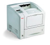
 1
1 235
235 236
236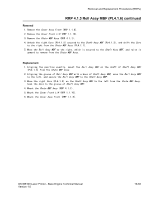 237
237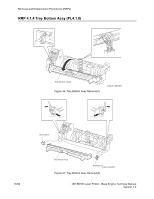 238
238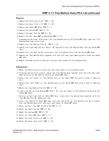 239
239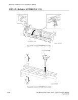 240
240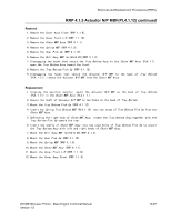 241
241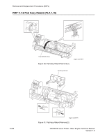 242
242 243
243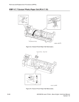 244
244 245
245