Panasonic BT-LH1850 Brochure - Page 4
I/P Conversion Circuit for Motion Response - bt 300
 |
View all Panasonic BT-LH1850 manuals
Add to My Manuals
Save this manual to your list of manuals |
Page 4 highlights
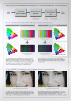
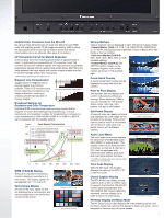
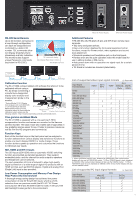
Faithful Color Correction from the 3D-LUT By using a three-dimensional LUT (Look Up Table) for each RGB color and applying precise 10 bit image processing, faithful colors are reproduced from low to high luminance levels and natural intermediate colors are attained. (See page 2 for details.) I/P Conversion Circuit for Motion Response A circuit delay time (not including panel delay) of approximately 5 msec* is achieved by incorporating an I/P converter circuit that converts SD and HD interlace signals with high precision to generate progressive signals without causing field-length delay. Minimizing the delay between the input signal and monitor output enables the user to confirm footage without any incongruity. * Differs slightly depending on the signal format. Diagonal Line Compensation Jagged noise on diagonal lines in moving images is a common problem. These LCD monitors solve this by detecting correlations in the diagonal direction, resulting in smooth, precise reproduction of moving images. Broadcast Settings for Gradation and Color Temperature Individual RGB corrections are made on every monitor that is shipped, to ensure that rated gamma properties (g = 2.2) are reproduced, and gradation suitable for broadcasting is achieved. A color temperature of 9300 K/6500 K/5600 K, or 3000 K to 9300 K, can be selected with the variable setting. Output 250 200 Panel Gamma Characteristics Yr (actual panel measurement value) Yg (actual panel measurement value) Yb (actual panel measurement value) Yr (target value) Yg (target value) Yb (target value) Varying errors in each panel Errors Corrected 100 Gamma curve --> power of 2.2 50 0 0 50 100 150 200 250 300 Input WFM (Y/R/G/B) Display The built-in waveform monitoring function displays a waveform in a sub-screen. The display signal can be selected from Y, R, G and B. Vectorscope Display All lines of the input signal via SDI are displayed as a vectorscope, and can be positioned in any of the four corners of the screen. Waveform Monitoring Vectorscope Display Various Markers Various markers can be displayed in both 16:9 and 4:3 aspect ratios. • Aspect Marker (16:9): 4:3, 13:9, 14:9, CNSCO2.39, CNSCO2.35, 2:1 or VISTA, with background brightness control of Black (0%), Half (50%) or Normal (100%). • Safe Area Marker (16:9/4:3): 95%, 93%, 90%, 88%, 80% or VAR (variable setting). • Center Marker (16:9/4:3): ON/ OFF. The center marker can be displayed together with another marker, as shown in the example right. Safe Area and Center Marker Cross Hatch Overlay A simple cross hatch overlay can be displayed to check the tilt of the camera. Pixel-to-Pixel Display This function lets you display and confirm video pixels without any resizing. When displaying 1080i/p, you can choose from five display areas: center, right-top, rightbottom, left-top or left-bottom. Cross Hatch ON Still Frame Display A frame of video can easily be frozen and displayed as a still image on the left side of the screen. This function can be used to match a live camera with a frame of video shot at an earlier time or with a different camera. Pixel-to-Pixel Display Image (1080i, center mode) Audio Level Meter The color audio level meter displays the input level of embedded audio (SDI, HDMI*) or analog audio.* The display mode can be selected from 2-channel, 4-channel, 8-channel or OFF. And it's equipped with reference point setting, peak hold and over-range display functions. * For HDMI or analog audio input, the level meter displays only two channels. Time Code Display With HD SDI input, this function displays the value of the VITC, LTC or UB time code. Closed Caption Display The BT-LH1850 can display closed captions with an SDI or VIDEO input. It supports the EIA/CEA-708 HD SDI closed captioning standard (EIA/ CEA-608 SD-SDI closed captioning standard), and can display up to eight windows simultaneously. Still Video Monitor Audio Level Meter Time Code Display Closed Caption Display HV Delay Display and Mono Mode The HV Delay function that displays the video blanking period, and the Mono mode that switches the display to black-and-white, can be assigned to function keys for quick access. 3
-
 1
1 -
 2
2 -
 3
3 -
 4
4 -
 5
5 -
 6
6
 |
 |
