Panasonic CF-72X3UUBDM Service Manual
Panasonic CF-72X3UUBDM - Toughbook 72 - Pentium 4-M 1.8 GHz Manual
 |
UPC - 092281823119
View all Panasonic CF-72X3UUBDM manuals
Add to My Manuals
Save this manual to your list of manuals |
Panasonic CF-72X3UUBDM manual content summary:
- Panasonic CF-72X3UUBDM | Service Manual - Page 1
ORDER NO. CPD0010001C0 Notebook Computer CF-72 This is the Service Manual for the following areas. M ...for U.S.A. and Canada E ...for B: CD-ROM drive C: CD-ROM drive / SuperDisk drive WARNING This service information is designed for experienced repair technicians only and is not designed for - Panasonic CF-72X3UUBDM | Service Manual - Page 2
For U.K. WARNINGS FOR YOUR SAFETY PLEASE READ THE FOLLOWING TEXT CAREFULLY This appliance is supplied with a moulded three pin mains plug for your safety and convenience. A 3 amp fuse is fitted in this plug. Should the fuse need to be replaced please ensure that the replacement fuse has a rating - Panasonic CF-72X3UUBDM | Service Manual - Page 3
. METTRE AU RÉBUT LES PILES USAGÉES CONFORMÉMENT AUX INSTRUCTIONS DU FABRICANT. For U.S.A. LASER SAFETY INFORMATION Class 1 LASER-Product The serviceman should not remove the cover of drive unit and should not service because the drive unit is a nonserviceable part. • Unplug the AC power - Panasonic CF-72X3UUBDM | Service Manual - Page 4
Contents 1. Specifications ...2. Name and Functions of Parts 3. Technical information ...3.1. System Overview ...3.2. System Memory Map ...3.3. I/O Address Map ...4. Diagnosis Procedure ...4.1. Basic Procedures ...4.2. Power-On Self Test (Boot Check 4.3. List of Error Codes ...4.4. Diagnosis Map - Panasonic CF-72X3UUBDM | Service Manual - Page 5
1. Specifications This page provides the specifications for the basic model CF-72N3FxZxx. The model number will change depending on the configuration of the unit, such as, CPU speed, memory size, HDD size and Operating System. To check the model number: Check the bottom of the computer or the box - Panasonic CF-72X3UUBDM | Service Manual - Page 6
Speaker Speaker (built in) x 4 Utility Programs Setup Utility, DMI Viewer, Panasonic Hand Writing*4 Sound Battery Pack HRTF 3D positional audio support 16-bit stereo, WAVE and MIDI playback Li-ion 10.8 V, 3.0 Ah Operating Time*5 Approx. 1.0 hours - 6.0*6hours Battery Charging Time*5 Power - Panasonic CF-72X3UUBDM | Service Manual - Page 7
and in-the-field efficiency. Security Lock LOCK A cable can be connected to prevent theft of your computer. For more information, read the manual that comes with the cable. Power Switch Before using the computer for the first time, carefully read the [Limited Use License Agreement]. If you - Panasonic CF-72X3UUBDM | Service Manual - Page 8
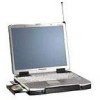
DC-IN Jack USB Ports RAM Module Slot Infrared Communication Port External Keyboard/Mouse Port Serial Port Parallel Port External Display Port Ventilation Hole These holes allow heat to exit. CAUTION Do not block or place the computer in a location that may prevent proper ventilation. Battery - Panasonic CF-72X3UUBDM | Service Manual - Page 9
3.Technical Information 3.1 System Overview 3.1.1 System Configuration The main system is made up of a Main board, a SUB board, a LED board, a PAD board and a LID board. The CPU operates at 1.6V, 1.35V(core)/2.5V; the main memory at 3.3V; the core logic at 3.3V/5V; and the other main chips at 3.3V. - Panasonic CF-72X3UUBDM | Service Manual - Page 10
System Configuration Diagram intel Mobile Pentium III 1.5V GTL 64bit Host Bus LCD 13.3 " CRT VRAM 8.0MB VGA Rage Mobility M, ATI CD-ROM X24max SuperDISK Secondary (120MB) Primary IDE Interface HDD 20GB2.5inch USB Selector Interface PCI ISA Bridge PIIX4M INTEL USB x2 DEVICES AGP - Panasonic CF-72X3UUBDM | Service Manual - Page 11
3.2 System Memory Map 3 - 3 - Panasonic CF-72X3UUBDM | Service Manual - Page 12
I/O Address Map (CF-72) Address x0000 - x000F x0010 - x0018 x001F - x001F x0020 - x0021 x0022 - x0022 x0024 - x0025 x0028 - x0029 x002C - x002D x0030 - x0031 x0034 - x0035 x0038 - x0039 x003C - x003D x0040 - x0043 x0050 - x0052 x0060 - x0060 x0061 - x0061 x0062 - x0062 x0064 - x0064 x0066 - x0066 - Panasonic CF-72X3UUBDM | Service Manual - Page 13
are summarized below. For details, refer to relevant pages in the Service Manual. l Flow Chart OCCURRENCE OF TROUBLE Power sw is set to ON. Power On Self Test Automatic diagnosis test when it is necessary for conduct trouble diagnosis. TROUBLESHOOTING Defective parts are sorted by referring to - Panasonic CF-72X3UUBDM | Service Manual - Page 14
controller error RAM error RAM error RAM error BIOS ROM error Occurrence of unexpected offering (Note) A beep sound is also issued in case of other I/O trouble. 4 - 2 - Panasonic CF-72X3UUBDM | Service Manual - Page 15
Following the list are explanations of the messages and remedies for reported problems. If your system displays one of except the messages marked below with an asterisk (*), write down the message and contact Panasonic Technical Support. If your system fails after you make changes in the Setup menus - Panasonic CF-72X3UUBDM | Service Manual - Page 16
System cache error - Cache disabled Contact Panasonic Technical Support. 02F0: CPU ID: CPU socket number for Multi address of the failure in System, Extended or Shadow memory. Invalid System Configuration Data Problem with NVRAM (CMOS) data. I/O device IRQ conflict I/O device IRQ conflict error. - Panasonic CF-72X3UUBDM | Service Manual - Page 17
unit. (when using AC) No power is sent to the unit, (When using the Battery Pack) 2 Power cuts off during operation. Troubleshooting No. procedures Result Source of problem Component 1-1 Is 15V applied to pins 5-8 of Q74? (Whichever one)? YES NO Go to No. 1-6 Go to No. 1-2 1-2 Is 15V - Panasonic CF-72X3UUBDM | Service Manual - Page 18
Date and Time are not displayed. 3 Memory count is too large or too small. 4 No Sound Volume does not work. Troubleshooting No. procedures Result Source of problem 2-1 Replace the Main PCB. Main PCB 3-1 Replace the Main PCB. Main PCB 4-1 Check software setting. YES Software setting NO Go - Panasonic CF-72X3UUBDM | Service Manual - Page 19
13 Real time Clock is not updating 14 Memory size/data error 15 PCI failur No. 13-1 14-1 15-1 15-2 Troubleshooting procedures Does resetting the date/time in SETUP correct the problem? Replace the expansion RAM card. Does operation return to normal? (Go to "NO" if not connected.) Does the system - Panasonic CF-72X3UUBDM | Service Manual - Page 20
not function. Input from the track ball are not accepted properly. 6 Keyboard failure 7 Keyboard interface failure Troubleshooting No. procedures Result Source of problem 1-1 Keyboard is broken. Keyboard Replace the keyboard and YES Keyboard 2-1 see if inputting from the keyboard function - Panasonic CF-72X3UUBDM | Service Manual - Page 21
Make sure that connecting cables, connectors and AC adapter are not loose or disconnected prior to testing. No. Symptom Troubleshooting No. procedures Result Source of problem Component 1 Access lamp does not light. 1-1 Replace the SDD. Does operation return to YES SDD normal? NO Go - Panasonic CF-72X3UUBDM | Service Manual - Page 22
Make sure that connecting cables, connectors and AC adapter are not loose or disconnected prior to testing. No. Symptom Troubleshooting No. procedures Result Source of problem 1 Does not boot from HDD. 1-1 Has the HDD been partitioned? YES Go to No. 1-2 NO Improper setting 1-2 Are there - Panasonic CF-72X3UUBDM | Service Manual - Page 23
communicate with another computer when connected directly. 3 Unit will not communicate with modem. 4 Diagnostic Test reports problem in serial port. Troubleshooting No. procedures Result Source of problem 1-1 Is the COM port properly set? YES NO Go to No. 1-2 Improper setting Is the same - Panasonic CF-72X3UUBDM | Service Manual - Page 24
to testing. No. Symptom 1 Access lamp does not light. 2 Cannot read from DVD. 3 Tray does not open. 4 Abnormal sound. Troubleshooting Source of No. procedures Result problem Replace the CD-ROM drive. YES CD-ROM drive 1-1 Does operation return to normal? NO Go to No. 1-2 Replace the - Panasonic CF-72X3UUBDM | Service Manual - Page 25
and AC adapter are not loose or disconnected prior to testing. No. Symptom 1 Data cannot be sent or received. Troubleshooting No. procedures Result Source of problem 1-1 Is the Infrared Communication Port enabled in Setup? YES NO Go to No. 1-2 Improper setting Component Is the same - Panasonic CF-72X3UUBDM | Service Manual - Page 26
/2 mouse plug pin 3.) Connect pins 3-4-7-9-10-12 to VC5 (PS/2 mouse plug pin 4) with 4.7KW each. CAUTION The plug described above must be used for servicing purpose only. Do not use it for other than the above purpose and ensure that it remains confidential. Using the plug enables the user to - Panasonic CF-72X3UUBDM | Service Manual - Page 27
5.1.4 Test Procedure Use the floppy disk containing file diag48. Press [D] [I] [A] [G] [4] [8] and [Enter] keys. DIAGNOSTIC MENU (V*.*L**) 1. TEST ALL DEVICES ( DEVICES) 2. TEST AUTOMATICALLY ( DEVICES) 3. EXIT 4. MAIN BOARD 5. xxxxxKB RANDOM ACCESS MEMORY 6. KEYBOARD 7. TRACK BALL/MOUSE 8. BATTERY - Panasonic CF-72X3UUBDM | Service Manual - Page 28
3) KEYBOARD TEST Press 6 and Enter keys. KEYBOARD 1. TEST ALL DEVICES ( DEVICES) 2. TEST AUTOMATICALLY ( DEVICES) 3. EXIT 4. PRESS KEY TEST 5. SCAN CODE RETURN TEST SELECT MENU : _ For 4. PRESS KEY TEST. Press 4 and Enter Keys. PRESS KEY TEST 1. TEST ALL DEVICES ( DEVICES) 2. TEST - Panasonic CF-72X3UUBDM | Service Manual - Page 29
5) BATTERY PACK TEST Press 8 and Enter keys. BATTERY PACK TEST Battery Pack : exists. AC Adaptor : connected (Not connected) (Normal message) : Test done ! ! Press any key when ready._ When an error message is displayed, refer to [5.2 Error Massage]. 6) VIDEO TEST Press 9 and Enter keys. VIDEO - Panasonic CF-72X3UUBDM | Service Manual - Page 30
For 4. HDD - DRIVE TEST. Press 4 and Enter keys. 1st HDD - DRIVE TEST Count value to get SEEK COMPLETE = 0 (Normal Message) : Test done ! ! Press any key when ready._ When an error message is displayed, refer to [5.2 Error Message] For 5. HDD - READ/WRITE TEST. Press 5 and Enter keys. 1st HDD - Panasonic CF-72X3UUBDM | Service Manual - Page 31
For 5. 1st FLOPPY DISK DRIVE TEST. Press 5 and Enter keys. 1st FLOPPY DISK DRIVE TEST 1. TEST ALL DEVICES ( 2. TEST AUTOMATICALLY ( 3. EXIT 4. DRIVE TEST 5. 720KB - MEDIA TEST 6. 1.44MB - MEDIA TEST SELECT MENU : _ DEVICES) DEVICES) For 4. DRIVE TEST. Press 4 and Enter keys. 1st FLOPPY DISK - Panasonic CF-72X3UUBDM | Service Manual - Page 32
For 4. PRINT OUT TEST. Press 4 and Enter keys. 1st Parallel port test (I/O address xxxH) Connect printer Hit any key when ready._ (Normal Message): Sample characters will be printed to the printer. 1st Parallel port test (I/O address 378H 0123456789:;?@ABCDEFGHIJKLMNOPQRSTUVWXYZ[\]ˆ_` - Panasonic CF-72X3UUBDM | Service Manual - Page 33
For 4. RS232C CONTROLLER REGISTER R/W TEST. Press 4 and Enter keys. 1st serial port test (I/O address xxxH) (Normal Message): Test done ! ! Press any key when ready._ When an error message is displayed, refer to [5.2 Error Message]. For 5. INTERNAL LOOPBACK TEST. Press 5 and Enter keys. 1st - Panasonic CF-72X3UUBDM | Service Manual - Page 34
For 4. CONTROLLER REGISTER R/W TEST. Press 4 and Enter keys. CONTROLLER REGISTER R/W TEST Infrared port (I/O address xxxxH) (Normal Message): Test done ! ! Press any key when ready._ When an error message is displayed, refer to [5.2 Error Message]. For 5. INTERNAL LOOPBACK TEST. Press 5 and - Panasonic CF-72X3UUBDM | Service Manual - Page 35
5.2 Error Message 5 - 10 IC3 IC3 IC3 IC3 IC31 IC3 IC3 IC10-17 IC10-17 IC10-17 IC1 IC2 - Panasonic CF-72X3UUBDM | Service Manual - Page 36
IC3 IC31 IC31 IC5 IC5 IC5 5 - 11 - Panasonic CF-72X3UUBDM | Service Manual - Page 37
IC5 IC5 IC5 IC30 IC5 IC5 5 - 12 - Panasonic CF-72X3UUBDM | Service Manual - Page 38
IC5 IC28 IC33 IC49 IC3 5 - 13 - Panasonic CF-72X3UUBDM | Service Manual - Page 39
5 - 14 - Panasonic CF-72X3UUBDM | Service Manual - Page 40
5 - 15 - Panasonic CF-72X3UUBDM | Service Manual - Page 41
6. Disassembly/Reassembly Note: Power off the computer. Do not shut down to the Suspend or hibernation mode. Do not add peripherals while the computer is in the Suspend or hibernation mode; abnormal operation may result. 6.1 Removing the Battery Pack. 6.2 Removing the HDD Unit. Tab Slide - Panasonic CF-72X3UUBDM | Service Manual - Page 42
6.4 Removing the RAM Card. RAM Card Cover Palmrest Unit Open PAD PCB CN701 CN703 Figure 5 2. Turn open the palmrest unit. 3. Disconnect the two connectors CN701 and CN703. 4. Remove the two screws . 5. Remove the PAD PCB. Screw : XTB2+5GFN Pad Holder RAM Card Connector - Panasonic CF-72X3UUBDM | Service Manual - Page 43
CN801 KB Waterproof Turn CN802 Keyboard Figure 9 2. Turn the keyboard. 3. Open the KB waterproof. 4. Disconnect the two connectors CN801 and CN802. 5. Remove the keyboard Figure 11 Hooks 2. Release the hooks of the hinge cover L and the hinge cover R. 6.6 Removing the LCD Section and the - Panasonic CF-72X3UUBDM | Service Manual - Page 44
6.7 Removing the LCD Section and the LED PCB. LED Section LED 6.9 Removing the Bottom Case Unit and the Handle Unit. LED PCB Figure 15 1. Remove the two screws , and remove the LCD unit. 2. Remove the two screws , and remove the LED PCB. Screw : - Panasonic CF-72X3UUBDM | Service Manual - Page 45
6.11 Removing the Main PCB. Modem Jack Cover 6.12 Removing the Fan and the Fan Heat Angle. Open Lift Up Port Cover R Open Figure 18 Open Port Cover L 1. Remove the two screws . 2. Open the modem jack cover , port cover R and the port cover L. Screw : XTB2+5GFN Minus Screw Driver - Panasonic CF-72X3UUBDM | Service Manual - Page 46
6.13 Removing the Sub PCB. 6.15 Removing the Bus Shutter Unit and the Card Shutter Unit. Card Shutter Unit Power Knob Sub PCB Figure 23 1. Remove the two screws , and remove the power knob and the sub PCB. Screw : DFHE5020YB 6.14 Removing the LID PCB. Bus Shutter Unit - Panasonic CF-72X3UUBDM | Service Manual - Page 47
6.17 Removing the LCD Unit and the Inverter PCB. LCD Screw Sheets LCD Leg Rubbers LCD Unit Inverter Output Connector Figure 27 LCD Flont Cabinet 1. Remove the two LCD leg rubbers and the two screws . 2. Remove the two LCD screw sheets and the two screws . 3. Remove the LCD front - Panasonic CF-72X3UUBDM | Service Manual - Page 48
6.18 Removing the LCD Lock and the LCD Lock Spring. LCD Lock LCD Spring LCD Front Cabinet Figure 31 1. Remove the two screws . 2. Remove the LCD lock and the LCD lock spring. Screw : DFHE5119ZA 6.19 Setting the Dip SW 1. Set the dip switching (SW1) as follows. Main PCB Dip SW (SW1) 1 - Panasonic CF-72X3UUBDM | Service Manual - Page 49
7. Wiring Connection Diagram BACKLIGHT SPEAKER LARGE (LEFT) SPEAKER SMALL (LEFT) CN906 CN907 CN903 CN902 CN901 CN905 CN909 CN908 SPEAKER LARGE (RIGHT) SPEAKER SMALL (RIGHT) TOUCH SCREEN PANEL LCD PS2/MOUSE CN11 PARALLEL CN9 MINIPCI 2 VGA CN6 CN1 MINIPCI 1 SERIAL CN10 DIMM CARD CN7 - Panasonic CF-72X3UUBDM | Service Manual - Page 50
8. Exploded View K25 K84 E24 K120 K42 K14 K13 K119 K2 K26 K141 K38 E12 A K225 K30 A K230 A K230 K86 K31 K23 A K205 E15 A K205 Screw tightening torque A 0.2 ± 0.02N·m (2.0 ± 0.2kgf·cm) C 0.3 ± 0.03N·m (3.0 ± 0.3kgf·cm) D 0.5 ± 0.05N·m (5.0 ± 0.5kgf·cm) A K226 A K226 K112 E31 K44 K6 - Panasonic CF-72X3UUBDM | Service Manual - Page 51
K104 A K205 K20 B K222 E29 K224 K111 B K224 B K110 K40 K224 B K224 B K16 K224 A K222 E1 A A K229 K229 K53 A K223 E30 K19 K223 A K223A K151 A K223 K148 K108 K34 K20 E28 K7 A K222 K40 K222 A B K224 K109 K20 A K205 K12 K142 K1 K150 E26 E25 K107 K49 K35 K74 K149 - Panasonic CF-72X3UUBDM | Service Manual - Page 52
K87 K89 K164 K91 K94 K221 K70 K227 A K230 A K230 K71 K93 K79 K94 A K221 A K220 A K209 K90 K73 D D K231 K80 K231 K157 K122 K126 K127 E21 K129 K227 K77 K123 K98 A K209 A K220 K83 A K230 A K230 K95 K85 K126 K130 K98 K127 D K231 K98 K81 D K231 K98 A K209 K82 K72 A - Panasonic CF-72X3UUBDM | Service Manual - Page 53
CD-ROM Drive (CF-VCD711) K6 K5 E K101 K1 E4 K2 Hooks E1 K7 E2 K8 E3 K9 K4 K3 E K102 Screw tightening torque C 0.3 ± 0.03N·m (3.0 ± 0.3kgf·cm) E 0.176 ± 0.02N·m (1.8 ± 0.2kgf·cm) C K103 8 - 4 - Panasonic CF-72X3UUBDM | Service Manual - Page 54
SuperDisk Drive (CF-VFS712W) K1 C K101 K9 K8 K9 K6 K3 E4 Screw tightening torque C 0.3 ± 0.03N·m (3.0 ± 0.3kgf·cm) D 0.5 ± 0.05·m (5.0 ± 0.5kgf·cm) K4 K2 K7 Hooks E2 E3 E1 K5 K3 K9 K9 K6 C K101 D K102 8 - 5 D K102 - Panasonic CF-72X3UUBDM | Service Manual - Page 55
ADAPTER CGP-E/620B BATTERY PACK DFJA0047ZAKK AC CABLE DFJS535ZA CABLE, MODEM CF-VFS712W SUPERDISK DRIVE DFQX5160ZA OPERATING INSTRUCTIONS *OPERATING INSTRUCTIONS MANUAL Note: About the parts which written " * " above, please order to Computer Products Europe (CPE) written below Matsushita - Panasonic CF-72X3UUBDM | Service Manual - Page 56
REF. NO. and AREA Mechanical Parts K 1 K 2 K 3 K 4 K 5 K 6 K 7 K 8 K 9 K 10 K 11 K 12 K 13 K 14 K 15 K 16 K 17 K 18 K 19 K 20 K 22 K 23 K 24 K 25 K 26 K 27 K 27 -1 K 28 K 28 -1 K 29 K 30 K 31 K 32 K 33 K 34 K 35 K 36 K 37 K 38 K 39 K 40 K 41 K 42 K 43 K 44 K 45 K 46 K 49 K 50 K 51 K 51 -1 K 51 -2 K - Panasonic CF-72X3UUBDM | Service Manual - Page 57
, HDD HOLDER, CN, HDD COVER, HDD LABEL-M, UNIT LABEL-EU, UNIT SHEET, CABLE, PCI CLAMP, MINI PLATE, CONFIG, RJ45 ANGLE, PORT GUIDE (MAIN), CN GUIDE, CN, MP CUSHION, CHASSIS, HDD CUSHION , 2, CN, HDD GASKET, COVER, BATTERY BALANCER 1, HDD CENTER, CUSHION, PALMREST CUSHION, SC, PALMREST TAPE, CABLE - Panasonic CF-72X3UUBDM | Service Manual - Page 58
, FPC, KB SHEET, SLIDE, MP SPACER, UNDER, MP SHEET, 2, CABLE, LAMP SPACER, HINGE LABEL, HIGH VOLTAGE SHEET, CN, HDD HDD Mounting Kit for Support DUMPER, 2, HDD TEPE, BOTH SIDES XYN2+J12FZ XYN2+J16FN XYN2+J6FN XTB2+16GFN XTB2+5GFN XTB26+20GFN DXHM0021ZA DFHE5020YB DFHE5025XA DXQT2+G5FUBN DXQT2+H25L - Panasonic CF-72X3UUBDM | Service Manual - Page 59
(Main Block Unit, Mechanical Parts, Accessories and Packing Materrial) REF. NO. and AREA Main PCB C 2 385 386 C 3 4 388 C 14 15 16 17 41 42 117 121 125 129 152 312 313 314 345 C 18 19 20 21 23 24 25 26 28 29 30 31 32 33 34 36 37 38 39 40 49 50 53 54 55 56 59 60 68 70 71 74 103 104 105 108 109 110 - Panasonic CF-72X3UUBDM | Service Manual - Page 60
REF. NO. and AREA C 141 142 143 144 247 248 249 250 375 379 381 C 161 162 C 187 188 C 189 245 445 C 193 195 196 C 197 198 199 200 201 202 C 216 219 225 226 C 220 244 269 354 C 235 236 239 240 332 356 357 358 399 C237 238 C252 254 C 259 271 272 274 275 283 284 285 286 288 289 298 376 C 287 409 411 - Panasonic CF-72X3UUBDM | Service Manual - Page 61
REF. NO. and AREA CN 15 CN 16 CN 17 CN 18 CN 19 CN 20 CN 21 CN 22 CN 23 D 1 2 9 10 D 3 4 12 D 5 6 7 30 31 32 33 D 8 D 11 D 13 14 D 15 18 29 D 16 D 17 D 19 20 D 21 22 D 23 D 24 D 25 D 26 28 D 27 D 34 35 36 D37 F 1 F 2 IC 1 IC 2 IC 3 IC 4 IC 5 IC 6 IC 7 IC 8 IC 9 IC 10 12 14 16 IC 11 13 15 17 IC 18 44 - Panasonic CF-72X3UUBDM | Service Manual - Page 62
REF. NO. and AREA IC 35 IC 36 IC 37 IC 38 39 IC 40 41 IC 43 IC 45 IC 47 48 IC 49 IC 50 IC 51 IC 52 IC 53 IC 54 IC 55 IC 56 IC 57 IC 59 IC 60 IC 62 IC 65 JK 1 JK 2 JK 3 L 1 L 2 4 18 19 20 21 22 L 3 5 45 51 L 10 11 14 15 L 12 13 16 17 L 23 24 25 26 28 29 30 L 27 31 L 32 33 34 35 L 36 37 L 38 44 L39 40 - Panasonic CF-72X3UUBDM | Service Manual - Page 63
REF. NO. and AREA Q 24 53 Q 25 26 27 Q 29 30 Q 35 36 Q 47 R 1 R 4 24 R 5 13 83 R 6 14 15 R 7 R 8 R 9 10 54 55 56 57 58 59 60 61 62 145 170 171 345 350 379 R 11 23 36 264 R 12 82 R 16 26 100 106 229 230 368 R 17 40 46 72 74 80 81 89 90 108 111 114 167 214 222 223 224 249 285 321 347 377 378 386 428 R - Panasonic CF-72X3UUBDM | Service Manual - Page 64
REF. NO. and AREA R 159 199 202 212 213 216 225 254 261 R 160 R 162 R 166 R 173 385 R 176 209 R 180 181 382 R 182 R 184 200 233 R 185 186 187 207 R 189 190 381 R 191 192 193 R 198 241 242 243 253 R 210 211 R 215 227 228 R 219 R 235 R 247 248 R 250 R251 252 R 258 R 271 351 352 R 274 275 277 278 R 276 - Panasonic CF-72X3UUBDM | Service Manual - Page 65
REF. NO. and AREA RA 24 53 RA 26 27 28 32 34 36 37 38 RA 30 RA 39 40 42 RA 41 RA 43 RA 44 45 46 RA 49 RA 54 RA 55 SW 1 X 1 X 2 X3 5 X 4 LED PCB C 901 902 C 903 C 904 906 908 910 C 905 907 C 912 913 915 916 918 919 C 914 917 920 C 922 923 CN 901 CN 902 CN 903 CN 905 CN 906 908 CN 907 909 D 901 D 902 - Panasonic CF-72X3UUBDM | Service Manual - Page 66
REF. NO. and AREA C 802 812 815 C 808 811 C 810 C 816 C 818 829 C 819 820 822 851 C 821 C 823 C 824 C 826 848 C 827 C 828 C 830 CA 801 802 CN 801 CN 802 CN 803 CN 804 810 CN 805 CN 806 CN 808 CN 809 CN 811 CN 812 D 802 803 804 818 819 D 805 806 807 810 820 D 808 809 D 811 812 D 813 D 814 D 815 IC - Panasonic CF-72X3UUBDM | Service Manual - Page 67
REF. NO. and AREA R 807 R 808 809 R 810 R 812 R 815 R 816 844 849 854 871 R 818 819 820 869 R 824 R 825 R 827 R 828 R 830 870 R 831 835 836 839 846 872 874 877 881 883 R 832 R 833 R 834 R 837 R 838 R 840 R 841 R 842 R 843 853 885 R 845 R 847 R 848 855 R 850 851 R 852 R 867 868 R 876 RA 801 RA 802 - Panasonic CF-72X3UUBDM | Service Manual - Page 68
SCREW DFHE5086ZA SCREW DFJS250YA160 CONNECTOR, EXPANSION BUS DFJS120ZA050 CONNECTOR, FOR CONNECTOR (B) PC DFJS315ZA050 CONNECTOR, FOR DRIVE DFJS120ZA050 CONNECTOR, FOR CONNECTOR (A) PCB Refer to CF-VCD711 service manual. Q'TY RTL 1 RTL 1 1 1 1 1 1 1 2 1 1 1 1 2 2 2 1 1 1 1 9 - 14 - Panasonic CF-72X3UUBDM | Service Manual - Page 69
2 RATING LABEL 1 WASHER 4 SCREW 4 SCREW 4 CONNECTOR, EXPANSION BUS 1 CONNECTOR, FOR CONNECTOR (B) PCB 1 RESISTOR, 1/16W, 0¶ 2 CONNECTOR, FOR CONNECTOR (A) PCB 1 CONNECTOR, FOR DRIVE 1 Refer to CF-VFS712W service manual. 9 - 15
-
 1
1 -
 2
2 -
 3
3 -
 4
4 -
 5
5 -
 6
6 -
 7
7 -
8
-
9
-
10
-
11
-
12
-
13
-
14
-
15
-
16
-
17
-
18
-
19
-
20
-
21
-
22
-
23
-
24
-
25
-
26
-
27
-
28
-
29
-
30
-
31
-
32
-
33
-
34
-
35
-
36
-
37
-
38
-
39
-
40
-
41
-
42
-
43
-
44
-
45
-
46
-
47
-
48
-
49
-
50
-
51
-
52
-
53
-
54
-
55
-
56
-
57
-
58
-
59
-
60
-
61
-
62
-
63
-
64
-
65
-
66
-
67
-
68
-
69
 |
 |

ORDER NO. CPD0010001C0
CF-72
Notebook Computer
© 2000 Matsushita Electric Industrial Co., Ltd.
All rights reserved.
Unauthorized copying and
distribution is a violation of law.
Model Number Reference
This is the Service Manual for
the following areas.
M ...for U.S.A. and Canada
E
...for U.K.
G
...for Germany
F
...for France
S
...for Sweden
T
...for Italy
P
...for Spain
The models in the CF-72 series are numbered in accordance with the types of the CPU, LCD
and HDD etc. featured by the product.
WARNING
This service information is designed for experienced repair technicians only and is not designed for use by the general public.
It does not contain
warnings or cautions to advise non-technical individuals of potential dangers in attempting to service a product.
Products powered by electricity
should be serviced or repaired only by experienced professional technicians.
Any attempt to service or repair the product or products dealt with in
this service information by anyone else could result in serious injury or death.
Model No.CF-72
Z
LCD type
3:
for 13.3" TFT Color
HDD type / RAM size
F:
20 GB / 128 MB
Area
M: for U.S.A. and Canada
E:
for U.K.
G: for Germany
F:
for France
S:
for Sweden
T:
for Italy
Drive
B:
CD-ROM drive
C: CD-ROM drive / SuperDisk drive
CPU type
N: for Intel
Mobile Pentium
III
Processor 700 MHz
Operating System
C: Microsoft
Windows NT
D: Microsoft
Windows
2000
E: Microsoft
Windows
98