Panasonic CF-72X3UUBDM Service Manual - Page 41
Disassembly/Reassembly, 6.1. Removing the Battery Pack., 6.2. Removing the HDD Unit.
 |
UPC - 092281823119
View all Panasonic CF-72X3UUBDM manuals
Add to My Manuals
Save this manual to your list of manuals |
Page 41 highlights
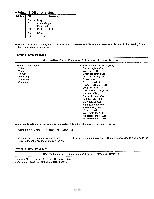
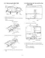
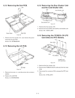
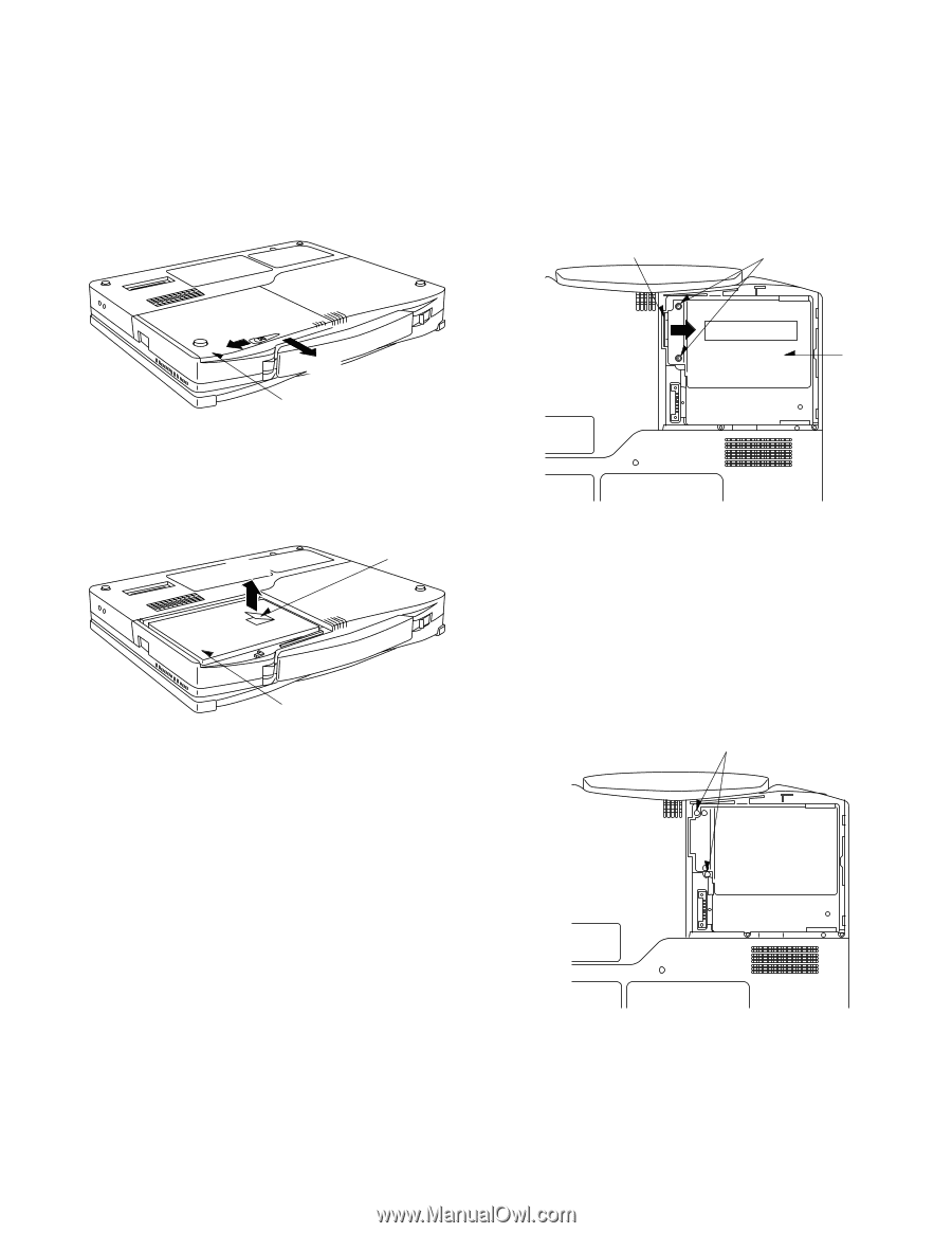
6. Disassembly/Reassembly Note: Power off the computer. Do not shut down to the Suspend or hibernation mode. Do not add peripherals while the computer is in the Suspend or hibernation mode; abnormal operation may result. 6.1 Removing the Battery Pack. 6.2 Removing the HDD Unit. Tab Slide Slide Battery Cover Unit Figure 1 1. Slide the latch, and then without releasing it, slide and remove the battery cover unit. Tab Lift up HDD Unit Figure 3 1. Remove the two screws . 2. Put down the tab, and lift up the HDD unit. Screw : DFHE5061ZA Battery Pack Figure 2 2. Lift up the tab and remove the battery pack. 6.3 Removing the Palmrest Unit, the PAD PCB and the Touch Pad. Figure 4 1. Remove the two screws . Screw : XTB2+16GFN 6 - 1
-
 1
1 -
2
-
3
-
4
-
5
-
6
-
7
-
8
-
9
-
10
-
11
-
12
-
13
-
14
-
15
-
16
-
17
-
18
-
19
-
20
-
21
-
22
-
23
-
24
-
25
-
26
-
27
-
28
-
29
-
30
-
31
-
32
-
33
-
34
-
35
-
 36
36 -
 37
37 -
 38
38 -
 39
39 -
 40
40 -
 41
41 -
 42
42 -
 43
43 -
 44
44 -
 45
45 -
 46
46 -
47
-
48
-
49
-
50
-
51
-
52
-
53
-
54
-
55
-
56
-
57
-
58
-
59
-
60
-
61
-
62
-
63
-
64
-
65
-
66
-
67
-
68
-
69
 |
 |
6 - 1
6. Disassembly/Reassembly
Note: Power off the computer. Do not shut down to the Suspend or hibernation mode.
Do not add peripherals while the computer is in the Suspend or hibernation mode;
abnormal operation may result.
6.1
Removing the Battery Pack.
Battery Pack
Tab
Lift up
Figure 2
2.
Lift up the tab and remove the battery pack.
6.2
Removing
the HDD Unit.
Figure 3
1.
Remove the two screws <V>.
2.
Put down the tab, and lift up the HDD unit.
Screw <V>: DFHE5061ZA
<V>
HDD Unit
Tab
Figure 1
1.
Slide the latch, and then without releasing it, slide and
remove the battery cover unit.
Slide
Battery Cover Unit
Slide
6.3
Removing the Palmrest Unit, the
PAD PCB and the Touch Pad.
Figure 4
1.
Remove the two screws <D>.
Screw <D>: XTB2+16GFN
<D>