Panasonic FV-08WQ1 FV-08WQ1 Owner's Manual (English) - Page 6
Installation I In new construction - continue
 |
View all Panasonic FV-08WQ1 manuals
Add to My Manuals
Save this manual to your list of manuals |
Page 6 highlights
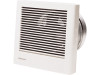
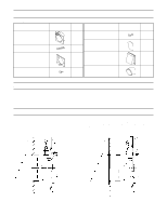
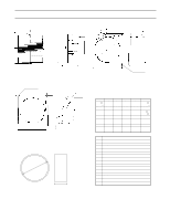
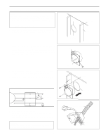
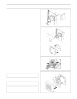
Installation I (In new construction) - continue 7. Insert the attached exterior hood from the outside to cover the wall sleeve, and secure it with four screws or nails. Cover the seam between the wall sleeve and exterior hood with aluminum tape, and apply mortar or caulking around the exterior hood flange to prevent rainwater from coming in. (Fig. 5) Exterior hood 8. Using enclosed template (pattern paper), mark and cut the opening in the interior wall cover. (Fig. 6) Aluminum tape Seam Interior wall material Finish with mortar or caulk. Fig. 5 9. Press the mounting plate tightly against the wall and secure to the outside of the wall sleeve with the supplied screws(screw II). (Fig. 7) 10. Remove the grille from the fan unit. Press the spring locks on the sides and pull the grille back. (Fig. 8) 11. Attach the electrical connectors to each other, hook the frame latches onto the mounting plate latch, and secure the fan unit to the mounting plate with the supplied screw (screw III). (Fig 9) CAUTION: Do not pinch the power cord with the frame. 12. Reattach the grille to the frame. CAUTION: Press on the grille until it clicks. NOTE: Be sure to paint the exterior hood. Before painting, thoroughly wipe off any oil on the surface. Also make sure that the paint does not enter inside of the hood. 6 Fig. 6 Fig. 7 Grille Fan unit (Frame) Fig. 8 Latch Latch Mounting plate Frame Grille Fig. 9
-
 1
1 -
 2
2 -
 3
3 -
 4
4 -
 5
5 -
 6
6 -
 7
7 -
 8
8 -
 9
9 -
 10
10
 |
 |
