Panasonic FV-08WQ1 Installation Instructions - Page 7
Installation, In remodeling
 |
View all Panasonic FV-08WQ1 manuals
Add to My Manuals
Save this manual to your list of manuals |
Page 7 highlights
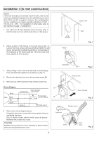
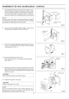
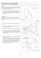
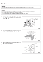
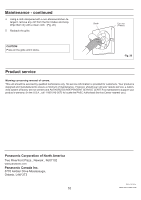
Installation II (In remodeling) NOTE: If the wall thickness is more than 152.4 mm (6"), refer to the reference installation drawing when the wall thickness is more than 152.4 mm (6") on page 2. 1. Cut holes in the interior and exterior walls. (Fig. 10) Cut a hole in the interior wall using the attached template (pattern paper), and make a 215 mm (8 1/2") hole in the exterior wall. Hole in the exterior wall CAUTION: The hole should be made in an area where pipes, cables and telephone lines are not run, and there are no studs in the way. Hole in the interior wall Fig. 10 2. Lay interior wiring through the wall using a flexible conduit. 3. Remove the junction box from the wall sleeve by removing two screws (C). (Fig. 11) 4. Remove the junction box cover by removing screw (B). 5. Remove the screws (D) and replace the wall sleeve flange with the mounting flange. (The mounting plate face should align with the end of the wall sleeve which is protruding from indoor side.) Junction box B D C Flange Wall sleeve Mounting plate Fig. 11 6. Attach the wall sleeve to the wall with supplied screws (Screw I). (Fig. 12) If the interior wall material is plaster board, use appropriate fasteners (locally available) to secure the wall sleeve. It is recommended to cover the seam between the wall sleeve and hole through the exterior wall with caulk, foam or mastic to prevent rainwater and air infiltration from coming into stud cavity. A hole where the junction box was attached to the wall sleeve. Fasterners, etc. Mounting plate Fig. 12 7
-
 1
1 -
 2
2 -
 3
3 -
 4
4 -
 5
5 -
 6
6 -
 7
7 -
 8
8 -
 9
9 -
 10
10 -
 11
11 -
 12
12 -
13
-
14
-
15
-
16
-
17
-
18
-
19
-
20
 |
 |
