Panasonic FV08VFL2 Installation Instructions
Panasonic FV08VFL2 Manual
 |
View all Panasonic FV08VFL2 manuals
Add to My Manuals
Save this manual to your list of manuals |
Panasonic FV08VFL2 manual content summary:
- Panasonic FV08VFL2 | Installation Instructions - Page 1
INSTRUCTIONS. Please read these instructions carefully before attempting to install, operate or service the Panasonic Ventilating Fan. Failure to comply with instructions ( Cleaning ) Maintenance II ( Replacement Of Lamp ) Practical Guide to Installation Product Service 2 2 3 3 4 4 4-5 6-8 8-9 10 10 - Panasonic FV08VFL2 | Installation Instructions - Page 2
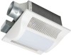
3 inches adaptor connector 1 (optional part) DESCRIPTION These Panasonic ceiling mount ventilation fans use a sirocco fan with dolphin-shaped blades driven by a capacitor motor. The motor is designed to have an extended service life with reduced energy consumption. It also incorporates a thermal - Panasonic FV08VFL2 | Installation Instructions - Page 3
/4 (45) 5 0 rn I II 13 (330) NMI i0MIMENM %WI 43/8 (110) 4 51/2 (141) 10 1/4 (261) 16 1/8 (410) J No. Part name 1 Grille 2 Adaptor 3 Fan body 4 Damper 5 Suspension bracket 6 Bracket cover 7 Junction box cover No. Part name 8 Junction box 9 Lighting unit 10 Fluorescent lamp 11 Night - Panasonic FV08VFL2 | Installation Instructions - Page 4
Accessories list to verify that all parts are present. GENERAL SAFETY INFORMATION 1. Do not install this ventilating fan where air temperature may exceed 40°C (104°F). 2. Make sure that the electric service supply voltage is 120 V, 60 Hz. 3. Follow all local electrical and safety codes, as well as - Panasonic FV08VFL2 | Installation Instructions - Page 5
ceiling, do not damage electrical wiring and other hidden utilities. E. Ducted fans must always be vented to the outdoors. F. These models are UL state control device. H. Before servicing or cleaning unit, switch power off at service panel and lock the service disconnecting means to prevent power - Panasonic FV08VFL2 | Installation Instructions - Page 6
shown below: Adaptor 7-A070 Damper RI MI I Clill Tape 2. Insert the suspension bracket into the fan body and adaptor. (Select the suspension bracket as shown below) A O Fan body Fig.1 Ca Fan body a Suspension bracket I Fig.2-1 a 0 Ili 1/i i1 i1 Joists Spacing A on center joists Insert - Panasonic FV08VFL2 | Installation Instructions - Page 7
screws (ST4.2X20) Fig.3-1 A=10 1/4-12 inches Joist 4. Install the suspension bracket to joists by using long screws (ST4.2X20) and secure it to the fan body by using screw II (ST4.2X12). (Fig.4) 5. Remove junction box cover and secure conduit or stress relief to junction box knock-out hole. (Fig - Panasonic FV08VFL2 | Installation Instructions - Page 8
Fig.6) 9. Insert the plug connector II and plug connector M into the receptacle If and receptacle III respectively, and secure the lighting unit to the fan unit with 2 screw III (ST4.2X16) and 1 machine screw (M4X8). (Fig.6) 10. Insert the fluorescent lamps and screw the night lamp into the lighting - Panasonic FV08VFL2 | Installation Instructions - Page 9
thumb screw and plug connector to receptacle. (Fig.10) 7. Secure the suspension bracket to joists by using long screws (ST4.2X20) and secure it to fan body by using screw II (ST4.2X12) in vertical direction. (Fig.11) 8. Follow step 8 to 11 of installation I (page 8) to complete the installation work - Panasonic FV08VFL2 | Installation Instructions - Page 10
INSTALLATION III ( I-JOIST MOUNTING ) 4 kinds of I-joist inches (mm) C1 9/16 (14.3) C2 11/16 (17.5) c C3 31/32 (24.6) C4 1 17/32 (38.9) Fan body C3 0 0 0 0 O C4 C1 C2 Suspension bracket III The suspension bracket DI can comply with different kinds of I-joist. Thumb screw Fig.13 CID - Panasonic FV08VFL2 | Installation Instructions - Page 11
B (7/8 inch, 21.6mm) for the thickness of ceiling board. Adaptor Fan body Junction box A 13 1/4-15 3/4 (336-400) 16 1/2-183/4 7/8 (21.6) 2 Long screws (ST4.2X20) Fig.17 5. Secure the suspension bracket to fan body by using screw II (ST4.2X12). (Fig.19) Joist 4 Long screws 2 Screw II - Panasonic FV08VFL2 | Installation Instructions - Page 12
Adaptor Wire nut Lead wires Green wires Fig.21 INSTALLATION VI ( IN EXISTING CONSTRUCTION ) 1. Installation in existing construction. Installing the fan body in an existing building requires an accessible area (attic or crawl space) above the planning installation location or existing ducting and - Panasonic FV08VFL2 | Installation Instructions - Page 13
on unit. Routine maintenance must be done every year. CAUTION: 1. Never use petrol, benzene, thinner or any other such chemicals for cleaning the ventilating fan. 2. Do not damp water to enter motor. 3. Do not soak resin parts in water over 60°C. 1. Remove grille. (Squeeze mounting spring and pull - Panasonic FV08VFL2 | Installation Instructions - Page 14
fill or batt insulation can be placed directly over the fan housing in the attic. Panasonic fans and fan/light combination units do not create excessive heat that is a common problem with recessed light fixtures or some competitors' fan/light combinations. Our efficient, cool-running motors and our
-
 1
1 -
 2
2 -
 3
3 -
 4
4 -
 5
5 -
 6
6 -
 7
7 -
8
-
9
-
10
-
11
-
12
-
13
-
14
 |
 |

INSTALLATION
INSTRUCTIONS
FV-05VFL2
FV-08VFL2
Ventilating
Fan
FV-11VFL2
FiI
1
Panasonid
READ
AND
SAVE
THESE
INSTRUCTIONS.
Please
read
these
instructions
carefully
before
attempting
to
install,
operate
or
service
the
Panasonic
Ventilating
Fan.
Failure
to
comply
with
instructions
could
result
in
personal
injury
and/or
property
damage.
Please
retain
this
booklet
for
future
reference.
Table
of
Contents
Supplied
Accessories
2
Description
2
Wiring
Diagram
3
Dimensions
3
Specifications
4
Unpacking
4
General
Safety
Information
4-5
Installation
I
(
Joist
Mounting
-I
)
6-8
Installation
II
(
Joist
Mounting
-II
)
8-9
Installation
III
(
I
-Joist
Mounting
)
10
Installation
IV(
Between
Joist
Mounting
)
10-11
Installation
V
(
Wooden
Header
)
11-12
Installation
VI
(
In
Existing
Construction
)
12
Maintenance
I
(
Cleaning
)
13
Maintenance
II
(
Replacement
Of
Lamp
)
13-14
Practical
Guide
to
Installation
14
Product
Service
14