Panasonic FV11VFL2 Installation Instructions - Page 3
Wiring, Diagram, Dimensions
 |
View all Panasonic FV11VFL2 manuals
Add to My Manuals
Save this manual to your list of manuals |
Page 3 highlights
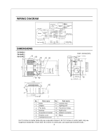
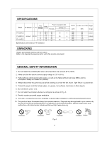
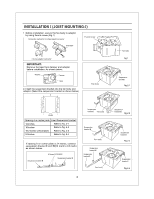
WIRING DIAGRAM Current Fuse 3.15 A Electronic Ballast Fluorescent Lamp Fan body Motor Red T Capacitor White White - White Black Black White White Black B ack Black Green Green Green Lighting unit Neutral Live Neutral Live Power Supply AC 120 V 60 Hz Earth ground Earth ground Night Lamp Junction box Black White Black I White Power Supply AC 120 V 60 Hz DIMENSIONS FV-05VFL2 FV-08VFL2 FV-11VFL2 0 Unit: inches(mm) 2 7/6 (73) 3 1/2 (90) 1 (26) 1 (25 8 13/4 (45) 5 0 rn I II 13 (330) NMI i0MIMENM %WI 43/8 (110) 4 51/2 (141) 10 1/4 (261) 16 1/8 (410) J No. Part name 1 Grille 2 Adaptor 3 Fan body 4 Damper 5 Suspension bracket 6 Bracket cover 7 Junction box cover No. Part name 8 Junction box 9 Lighting unit 10 Fluorescent lamp 11 Night lamp 12 Adaptor connector 13 Blade (For 16 inches on center joists,only use suspension bracket I, for 19.2 inches on center joists, only use suspension bracket IQ, If more than 19.2 inches on center joist, use suspension bracket II & 3
-
 1
1 -
 2
2 -
 3
3 -
 4
4 -
 5
5 -
 6
6 -
 7
7 -
 8
8 -
 9
9 -
10
-
11
-
12
-
13
-
14
 |
 |
