Panasonic FV30VQ3 FV10NLF1 User Guide - Page 6
appropriate duct
 |
View all Panasonic FV30VQ3 manuals
Add to My Manuals
Save this manual to your list of manuals |
Page 6 highlights
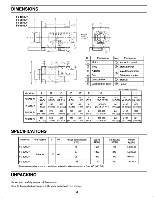
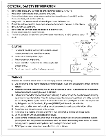
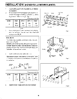
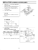
INSTALLATION I (HORIZONTALLYBETWEENJOISTS) 6. Attach the IN-LINE Fan to a joist or a pillar with the lOng screws. (FIg.4) 7. Remove junctionbox cover andsecureconduit or wire holder lo junction box cover knockout hole. (Fig.5) 8. Usingwire nuts,connect housepower wire asshown in the wiring diagram. 9. Replacejunction box cover. CAUTION Mount junctionbox cover carefully so that wires are not pinched. Law Saw Omar on Carmel:et Sawn Fie.a Wiring Diagram Pad / 5* aw ./.7" %Ns Noun/ Est 10. Installcircularducts (on both ends)and secure them with tape or clamps. Consult table3 for the appropriateduct sizes. Dimension: mm(inch) MODEL IONLFI 2ONLFI 3ONLFI 4ONLFI Orson 102 152 152 203 duct 93 (4) (6) (6) (8) Cord 0 (table 3) Juneon tot as Mre 11. Connectpower toe to receptacleafter finishingduct work. a uana tames Mak • F10.5 6
-
 1
1 -
 2
2 -
 3
3 -
 4
4 -
 5
5 -
 6
6 -
 7
7 -
 8
8 -
 9
9
 |
 |
