Panasonic KXTG5583M KXTG5583 User Guide - Page 77
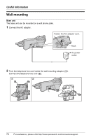
Useful Information, Connect the telephone line cord. Mount the unit by inserting the mounting pins
 |
View all Panasonic KXTG5583M manuals
Add to My Manuals
Save this manual to your list of manuals |
Page 77 highlights
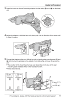
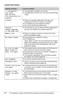
Useful Information 3 Insert the hooks on the wall mounting adaptor into the holes (A) and (B) on the base unit. A B B A 4 Adjust the adaptor to hold the base unit, then push it in the direction of the arrow until it clicks into place. 5 Connect the telephone line cord. Mount the unit by inserting the mounting pins (A and B) into the round openings on the adaptor, then sliding the unit down to secure the unit. L The position of the mounting pins may vary depending on the size of the wall mounting plate installed. Refer to the illustration below. L Raise the antennas. 83 mm (31/4") 102 mm (4") 83 mm (31/4") or 102 mm (4") For assistance, please visit http://www.panasonic.com/consumersupport 77
-
 1
1 -
2
-
3
-
4
-
5
-
6
-
7
-
8
-
9
-
10
-
11
-
12
-
13
-
14
-
15
-
16
-
17
-
18
-
19
-
20
-
21
-
22
-
23
-
24
-
25
-
26
-
27
-
28
-
29
-
30
-
31
-
32
-
33
-
34
-
35
-
36
-
37
-
38
-
39
-
40
-
41
-
42
-
43
-
44
-
45
-
46
-
47
-
48
-
49
-
50
-
51
-
52
-
53
-
54
-
55
-
56
-
57
-
58
-
59
-
60
-
61
-
62
-
63
-
64
-
65
-
66
-
67
-
68
-
69
-
70
-
71
-
 72
72 -
 73
73 -
 74
74 -
 75
75 -
 76
76 -
 77
77 -
 78
78 -
 79
79 -
 80
80 -
 81
81 -
 82
82 -
83
-
84
-
85
-
86
-
87
-
88
-
89
-
90
-
91
-
92
-
93
-
94
-
95
-
96
 |
 |

Useful Information
For assistance, please visit http://www.panasonic.com/consumersupport
77
3
Insert the hooks on the wall mounting adaptor into the holes (
A
) and (
B
) on the base
unit.
4
Adjust the adaptor to hold the base unit, then push it in the direction of the arrow until
it clicks into place.
5
Connect the telephone line cord. Mount the unit by inserting the mounting pins (
A
and
B
) into the round openings on the adaptor, then sliding the unit down to secure the
unit.
L
The position of the mounting pins may vary depending on the size of the wall
mounting plate installed. Refer to the illustration below.
L
Raise the antennas.
A
B
B
A
83 mm (3
1
/
4
")
or
102 mm (4")
83 mm
(3
1
/
4
")
102 mm
(4")