Panasonic NN-SA651S-RF NN-SA651S-RF Owner's Manual (English) - Page 11
oven COmpOnents Diagram
 |
View all Panasonic NN-SA651S-RF manuals
Add to My Manuals
Save this manual to your list of manuals |
Page 11 highlights
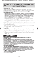
IP3518_39Y10AP_36_110630:IP3518_39Y10AP_00_110317.qxd 2011-6-30 Jerry 上上16:45 Page 9 oven components diagram o r su dq w q h g t i e q external air vent w internal air vent e door safety lock system r exhaust air vent t control Panel y identification Plate u glass tray i roller ring o heat/vapor barrier film (do not remove) r a ey f a Menu label s Warning label d Waveguide cover (do not remove) f door release button g Power supply cord h Power supply Plug 9
-
 1
1 -
2
-
3
-
4
-
5
-
 6
6 -
 7
7 -
 8
8 -
 9
9 -
 10
10 -
 11
11 -
 12
12 -
 13
13 -
 14
14 -
 15
15 -
 16
16 -
17
-
18
-
19
-
20
-
21
-
22
-
23
-
24
-
25
-
26
-
27
-
28
-
29
-
30
-
31
-
32
-
33
-
34
-
35
-
36
-
37
-
38
-
39
-
40
-
41
-
42
-
43
-
44
-
45
-
46
-
47
-
48
-
49
-
50
-
51
-
52
-
53
-
54
-
55
-
56
-
57
-
58
-
59
-
60
 |
 |

9
oven COmpOnents Diagram
q
External Air Vent
w
Internal Air Vent
e
DOOr Safety LOck System
r
ExHaust Air Vent
t
COntrOl Panel
y
IdentificatiOn Plate
u
Glass Tray
i
ROller Ring
o
heat/VapOr barrier Film
(do not remove)
a
Menu LaBel
s
Warning LaBel
d
Waveguide COver
(do not remove)
f
DOOr Release buttOn
g
POwer Supply COrd
h
POwer Supply Plug
s
o
r
u
d
q
w
t
h
r
a
y
e
f
i
e
g
q
IP3518_39Y10AP_36_110630:IP3518_39Y10AP_00_110317.qxd
2011-6-30
Jerry
16:45
Page 9