Panasonic NN-SD372 Operating Manual - Page 11
Operation
 |
View all Panasonic NN-SD372 manuals
Add to My Manuals
Save this manual to your list of manuals |
Page 11 highlights
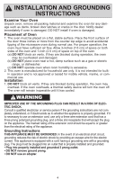
oven components diagram or d u d ya q wh j t f i e q external air vent w internal air vent e door safety lock system r exhaust air vent t control Panel y identification Plate u glass tray i roller ring o heat/vapor barrier film (do not remove) e g s a Waveguide cover (do not remove) s door release button d Warning label f Pop-out dial g Menu label h Power supply cord j Power supply Plug 9
-
 1
1 -
2
-
3
-
4
-
5
-
 6
6 -
 7
7 -
 8
8 -
 9
9 -
 10
10 -
 11
11 -
 12
12 -
 13
13 -
 14
14 -
 15
15 -
 16
16 -
17
-
18
-
19
-
20
-
21
-
22
-
23
-
24
-
25
-
26
-
27
-
28
-
29
-
30
 |
 |

9
oven COmpOnents Diagram
q
External Air Vent
w
Internal Air Vent
e
DOOr Safety LOck System
r
ExHaust Air Vent
t
COntrOl Panel
y
IdentificatiOn Plate
u
Glass Tray
i
ROller Ring
o
heat/VapOr barrier Film
(do not remove)
a
Waveguide COver
(do not remove)
s
DOOr Release buttOn
d
Warning LaBel
f
POp-out Dial
g
Menu LaBel
h
POwer Supply COrd
j
POwer Supply Plug
o
r
u
y
d
d
a
q
w
t
h
j
f
g
e
s
i
e