Panasonic PT-D5600U Dlp Projector- English/french - Page 32
How To Use Advanced Menu, Digital Cinema Reality, Blanking, Input Resolution, Clamp Pos.
 |
UPC - 791871111352
View all Panasonic PT-D5600U manuals
Add to My Manuals
Save this manual to your list of manuals |
Page 32 highlights
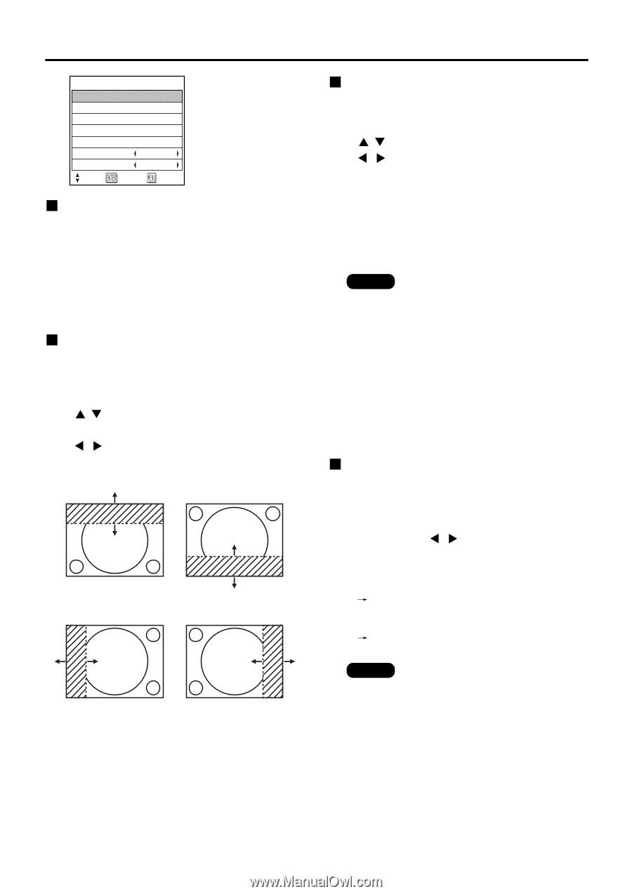
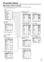
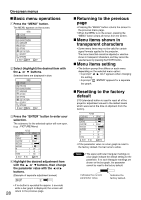
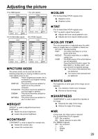
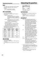
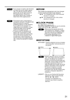
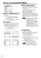
How to use ADVANCED MENU ADVANCED MENU DIGITAL CINEMA REALITY BLANKING INPUT RESOLUTION CLAMP POS. 1 RASTER POSITION XGA MODE XGA SXGA MODE SXGA SELSCT ENTER RETRN DIGITAL CINEMA REALITY (Only for input of S-Video/ Video/ YPBPR [480i, 576i] signals.) ON: Set at ON when you need to faithfully capture images shot at 24 frames per second as in movies. OFF: Set at OFF when unnatural images are obtained in the ON status. BLANKING You can perform fine adjustments for blanking if noise appears at the ends of the screen or the image protrudes out of the screen during image projection using a video deck and so on. : Select the UPPER, LOWER, LEFT or RIGHT adjustment. : Adjust the blanking width. For upper adjustment For lower adjustment For left adjustment For right adjustment INPUT RESOLUTION Input resolution adjustment achieves the best image when the screen flickers or halo is observed around the contour. : These select the items listed below. : These select the value. "TOTAL DOTS", "DISPLAY DOTS", "TOTAL LINES" and "DISPLAY LINES" Each item automatically displays a value in response to the type of the input signal. If vertical stripes appear on the screen or the image is partly missing, increase or decrease the displayed value while observing the screen to achieve the optimal value. Note • The abovementioned vertical stripes will not appear on the screen when all white signals are input. • The picture may be distorted during the adjusting operation, but this is not a fault. • The input resolution can be adjusted only when RGB signal input is applied with RGB1 and RGB2 IN. • Automatic adjustment is not available if signals having a dot clock frequency of more than 108 MHz are supplied. CLAMP POS. (For RGB/ YPBPR signals only) Use the clamp position adjustment to achieve the optimal value when dark areas of the image are crushed or displayed in green. Adjust with the buttons. The value changes from 0 to 255. The optimal value for the clamp position adjustment • If dark areas are crushed: The optimal value is the point where the dark area is best improved. • If the dark areas are displayed in green: The optimal value is the point where the green area becomes dark and clear. Note • The clamp position can be adjusted only when the RGB signal input is applied with RGB1 and RGB2 IN. 32
-
 1
1 -
2
-
3
-
4
-
5
-
6
-
7
-
8
-
9
-
10
-
11
-
12
-
13
-
14
-
15
-
16
-
17
-
18
-
19
-
20
-
21
-
22
-
23
-
24
-
25
-
26
-
 27
27 -
 28
28 -
 29
29 -
 30
30 -
 31
31 -
 32
32 -
 33
33 -
 34
34 -
 35
35 -
 36
36 -
 37
37 -
38
-
39
-
40
-
41
-
42
-
43
-
44
-
45
-
46
-
47
-
48
-
49
-
50
-
51
-
52
-
53
-
54
-
55
-
56
-
57
-
58
-
59
-
60
-
61
-
62
-
63
-
64
-
65
-
66
-
67
-
68
 |
 |