Panasonic TC-54PS14 Service Manual - Page 26
Initialization Pulse Adjust, P.C.B. Printed Circuit Board exchange, 1.3.1., Caution, 1.3.2., Quick
 |
View all Panasonic TC-54PS14 manuals
Add to My Manuals
Save this manual to your list of manuals |
Page 26 highlights
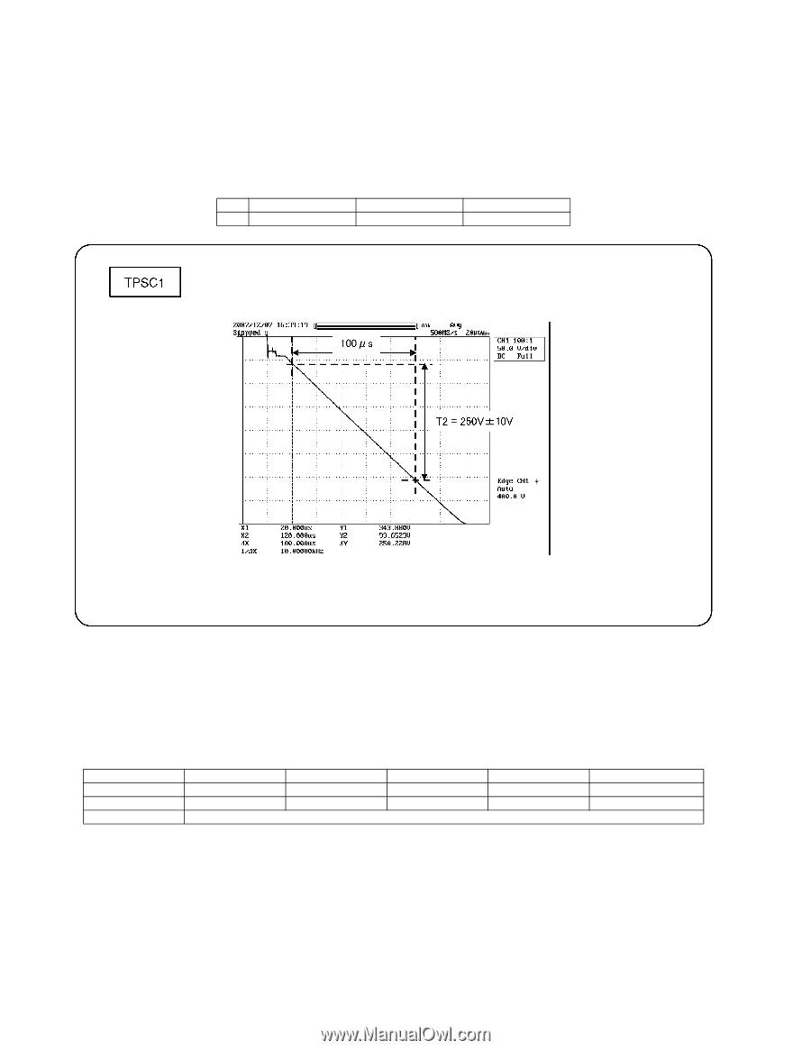
8.1.2. Initialization Pulse Adjust 1. Input the White signal to plasma video input. 2. Set the picture controls as follows. Picture menu : Vivid Normal : Set Aspect : Full 3. Connect Oscilloscope to TPSC1 (SC). Check the voltage (T2) at 100μs period on the down slop. Test point T2 TPSC1 (SC) Volume VR16601 (SC) Level 250 V ± 10 V 8.1.3. P.C.B. (Printed Circuit Board) exchange 8.1.3.1. Caution 1. To remove P.C.B., wait 1 minute after power was off for discharge from electrolysis capacitors. 8.1.3.2. Quick adjustment after P.C.B. exchange Adjust the following voltages with the multimeter. P.C.B. P Board SC Board A Board Name Test Point Voltage Volume Vsus TPVSUS (SS) Vsus ± 2V VR251 (P) * Vad TPVAD (SC) - 175V ± 2V VR16600 (SC) White balance and Sub brightness for NTSC, PAL, HD, PC and 625i signals *See the Panel label. Caution: Absolutely do not reduce Vsus below Ve not to damage the P.C.B. Remarks 26
-
 1
1 -
2
-
3
-
4
-
5
-
6
-
7
-
8
-
9
-
10
-
11
-
12
-
13
-
14
-
15
-
16
-
17
-
18
-
19
-
20
-
 21
21 -
 22
22 -
 23
23 -
 24
24 -
 25
25 -
 26
26 -
 27
27 -
 28
28 -
 29
29 -
 30
30 -
 31
31 -
32
-
33
-
34
-
35
-
36
-
37
-
38
-
39
-
40
-
41
-
42
-
43
-
44
-
45
-
46
-
47
-
48
-
49
-
50
-
51
-
52
-
53
-
54
-
55
-
56
-
57
-
58
-
59
-
60
-
61
-
62
-
63
-
64
-
65
-
66
-
67
-
68
-
69
-
70
-
71
-
72
-
73
-
74
-
75
-
76
-
77
-
78
-
79
-
80
-
81
-
82
-
83
-
84
-
85
-
86
-
87
-
88
-
89
-
90
-
91
-
92
-
93
-
94
-
95
-
96
-
97
-
98
-
99
-
100
-
101
-
102
-
103
-
104
-
105
-
106
-
107
-
108
-
109
-
110
-
111
-
112
-
113
-
114
-
115
-
116
-
117
-
118
-
119
-
120
-
121
 |
 |