Panasonic TY-42TM6D Operating Instructions - Page 7
Connections - video board
 |
UPC - 037988158102
View all Panasonic TY-42TM6D manuals
Add to My Manuals
Save this manual to your list of manuals |
Page 7 highlights
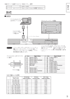
Slot Nos. of the PDP unit that are compatible with terminal board attachments. 37inch 42inch 50inch Slot1, Slot2 Slot1, Slot2 ( Slot3 is not compatible ) Connections Setup Example PC with digital RGB video out Plasma display rear panel English Digital RGB video cable (accessory) Mini-jack (M3) AUDIO RGB(digital)IN TBMU310 PET SLOT 1 2 3 AUDIO Notes: SLOT1 SLOT2 SLOT3 • If your PC does not support the plug-and-play capability (DDC1/2B) for displays, it will require reconfiguration after the display is connected to the PC. PC IN SERIAL Connect PC's video and audio outputs. Use this port to control the Plasma display from your PC. (Read the User's Manual supplied with the Plasma display.) Digital RGB Input Connector Pin Layouts Connection port view Pin No. Signal Name T.M.D.S. data 2- T.M.D.S. data 2+ T.M.D.S. data 2/4 shielded T.M.D.S. data 4- T.M.D.S. data 4+ DDC clock DDC data T.M.D.S. data 1T.M.D.S. data 1+ T.M.D.S. data 1/3 shielded T.M.D.S. data 3- Pin No. Signal Name T.M.D.S. data 3+ +5 V DC Ground Hot plug sense T.M.D.S. data 0- T.M.D.S. data 0+ T.M.D.S. data 0/5 shielded T.M.D.S. data 5- T.M.D.S. data 5+ T.M.D.S. clock shield T.M.D.S. clock+ T.M.D.S. clock- Applicable input signals Signal name Horizontal frequency(kHz) 1 525 (480) /60p 2 625 (575) /50p 3 750 (720) /60p 4 1,125 (1,080) /60i 5 640 × 480 @60Hz 6 852 × 480 @60Hz 7 800 × 600 @60Hz 8 1,024 × 768 @60Hz 9 1,066 × 600 @60Hz 10 1,366 × 768 @60Hz 31.47 31.25 45.00 33.75 31.47 31.50 37.88 48.36 37.88 48.36 Vertical frequency(Hz) 59.94 50.00 60.00 59.94 59.94 60.00 60.32 60.00 60.32 60.00 Dot clock frequency(MHz) 27.00 29.00 74.25 74.25 25.17 33.55 40.00 65.00 53.30 86.75 7
-
 1
1 -
 2
2 -
 3
3 -
 4
4 -
 5
5 -
 6
6 -
 7
7 -
 8
8 -
 9
9 -
 10
10 -
 11
11 -
 12
12 -
13
-
14
-
15
-
16
-
17
-
18
-
19
-
20
-
21
-
22
-
23
-
24
-
25
-
26
-
27
-
28
-
29
-
30
-
31
-
32
-
33
-
34
-
35
-
36
 |
 |
