Panasonic WJHD309 WJHD309 User Guide - Page 92
About the SETUP MENU, Main menu, Live image, Main area, Submenu, Notes
 |
View all Panasonic WJHD309 manuals
Add to My Manuals
Save this manual to your list of manuals |
Page 92 highlights
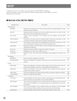
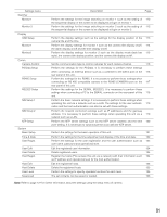
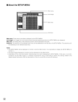
I About the SETUP MENU SET UP MENU Maintenance Recording Switcher Display Event Comm Schedule System REC Rate Disk Info Version Info Disk End Mode Disk Capacity Date Delete Event Log Error Log Access Log CAM 1 CAM 2 CAM 3 CAM 4 CAM 5 CAM 6 CAM 7 CAM 8 CAM 9 CAM 10 CAM 11 CAM 12 CAM 13 CAM 14 CAM 15 CAM 16 MANU AUTO AUTO AUTO AUTO AUTO AUTO AUTO AUTO AUTO AUTO AUTO AUTO AUTO AUTO AUTO AUTO SCHE 1ips 1ips 1ips 1ips 1ips 1ips 1ips 1ips 1ips 1ips 1ips 1ips 1ips 1ips 1ips 1ips PRE EVT POST EVT 1ips 1ips 1ips 1ips 1ips 1ips 1ips 1ips 1ips 1ips 1ips 1ips 1ips 1ips 1ips 1ips 1ips 1ips 1ips 1ips 1ips 1ips 1ips 1ips 1ips 1ips 1ips 1ips 1ips 1ips 1ips 1ips EMR 1ips 1ips 1ips 1ips 1ips 1ips 1ips 1ips 1ips 1ips 1ips 1ips 1ips 1ips 1ips 1ips LIVE SUPER FINE FINE NORMAL EXTENDED Main menu Live image Main area Submenu Main menu: These menus are always displayed on the SETUP MENU. Live image: Live images from the camera channel that was selected just before the SETUP MENU was displayed. Main area: The setting items of the selected submenu will be displayed in this area. Submenu: The submenu of the selected main menu will be displayed on the left side of the SETUP MENU. The submenus dif- fer depending on the selected main menu. Notes: • The SETUP MENU will be displayed on monitor 2 and the VGA monitor. (It is impossible to display the SETUP MENU on monitor 1.) • The same images displayed on monitor 2 will be displayed on the VGA monitor. • Depending on the connected monitor, flickering may occur when displaying the SETUP MENU. In this case, it is recommended to use the VGA monitor or a dirtectly connected PC using a LAN cable to perform the settings. (Refer to the Network Setup Instructions (PDF) for descriptions of how to connect this unit and a PC directly.) 92
-
 1
1 -
2
-
3
-
4
-
5
-
6
-
7
-
8
-
9
-
10
-
11
-
12
-
13
-
14
-
15
-
16
-
17
-
18
-
19
-
20
-
21
-
22
-
23
-
24
-
25
-
26
-
27
-
28
-
29
-
30
-
31
-
32
-
33
-
34
-
35
-
36
-
37
-
38
-
39
-
40
-
41
-
42
-
43
-
44
-
45
-
46
-
47
-
48
-
49
-
50
-
51
-
52
-
53
-
54
-
55
-
56
-
57
-
58
-
59
-
60
-
61
-
62
-
63
-
64
-
65
-
66
-
67
-
68
-
69
-
70
-
71
-
72
-
73
-
74
-
75
-
76
-
77
-
78
-
79
-
80
-
81
-
82
-
83
-
84
-
85
-
86
-
 87
87 -
 88
88 -
 89
89 -
 90
90 -
 91
91 -
 92
92 -
 93
93 -
 94
94 -
 95
95 -
 96
96 -
 97
97 -
98
-
99
-
100
-
101
-
102
-
103
-
104
-
105
-
106
-
107
-
108
-
109
-
110
-
111
-
112
-
113
-
114
-
115
-
116
-
117
-
118
-
119
-
120
-
121
-
122
-
123
-
124
-
125
-
126
-
127
-
128
-
129
-
130
-
131
-
132
-
133
-
134
-
135
-
136
-
137
-
138
-
139
-
140
-
141
-
142
-
143
-
144
-
145
-
146
-
147
-
148
-
149
-
150
-
151
-
152
-
153
-
154
-
155
-
156
-
157
-
158
-
159
-
160
-
161
-
162
-
163
-
164
 |
 |
