Panasonic WVCP460 WVCP460 User Guide - Page 4
Focus Or Flange-back Adjustment, Installation Of Camera
 |
View all Panasonic WVCP460 manuals
Add to My Manuals
Save this manual to your list of manuals |
Page 4 highlights
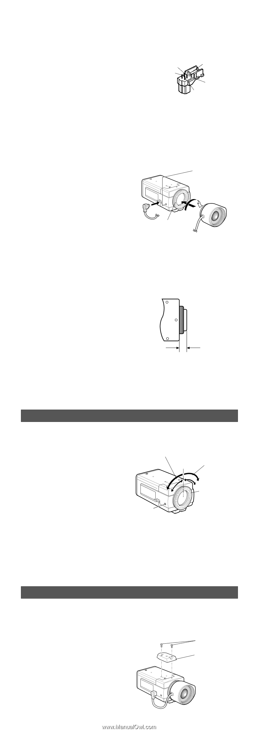
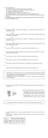
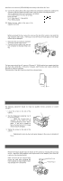
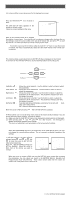
Installation of Auto Iris Lens Connector Install the lens connector (YFE4191J100) when using a video drive ALC lens. The installation should be made by qualified service personnel or system installers. (1) Cut the iris control cable at the edge of the lens connector to remove the existing lens connector and then remove the outer cable cover as shown in the diagram below. The pin assignment of the lens connector is as follows: Pin 1: Power source; +9 V DC, 50 mA max. Pin 2: Not used Rib Pin 3 Pin 3: Video signal; 1.3 V[p-p]/40 kΩ Pin 1 Pin 4: Shield, ground Pin 4 (2) Solder the lens cable to the pins of the Pin 2 supplied connector. Mounting the Lens Caution: Before you mount the lens, loosen the screw on the side of the camera, and rotate this ring clockwise until it stops. If the ring is not at the end, the inner glass or CCD image sensor may be damaged. 1. Mount the lens by turning it clockwise on the lens mount of the camera. 2. Connect the lens cable to the auto iris lens connector on the side of the camera. Screw q w Flange-back Adjusting Ring Caution for Mounting the Lens The lens mount should be a C-mount or CS-mount (1"-32UN) and the lens weight should be less than 450 g (0.99 lbs). If the lens is heavier, both the lens and camera should be secured by using the supporter. The protrusion at the rear of the lens should be as shown below: C-mount: Less than 13 mm (1/2") CS-mount: Less than 8 mm (5/16") FOCUS OR FLANGE-BACK ADJUSTMENT The following adjustment should be made by qualified service personnel or system installers. 1. Loosen the screw on the side of the camera. 2. Turn the flange-back adjusting ring to the desired position. Caution: When the C-mount lens is mounted, do not rotate the ring counterclockwise by force after it stops. If the ring is rotated by force, the inner lens or CCD image sensor may be damaged. Focusing of CS-mount lens Screw Focusing of C-mount lens Flange-back Adjusting Ring 3. Tighten the screw on the side of the camera. Caution: Tightening the screw by force will cause damage to the screw or deviation of focus. INSTALLATION OF CAMERA • Mounting from the top Remove the mount adapter from the bottom of the camera by removing the two fixing screws. Attach the mount adapter to the top as shown in the diagram, then mount the camera on the mounting bracket. Make sure that the two original fixing screws are used when mounting the mount adapter as longer length screws may damage inner components. Fixing Screws Mount Adapter
-
 1
1 -
 2
2 -
 3
3 -
 4
4 -
 5
5 -
 6
6 -
 7
7 -
 8
8 -
 9
9 -
 10
10 -
11
 |
 |