Panasonic WVNW474S WVNW474S User Guide - Page 8
Major Operating Controls & Their Functions Link Led Off Led On Rcv, Down Button Down
 |
View all Panasonic WVNW474S manuals
Add to My Manuals
Save this manual to your list of manuals |
Page 8 highlights
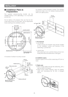
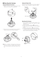
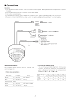
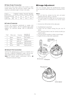
MAJOR OPERATING CONTROLS & THEIR FUNCTIONS u i !0 !1 LINK RCV !8 LEFT RIGHT UP DOWN SET !9 LED LED OFF ON A B o !2 !3 !4 !5 !6 !7 LINK RCV LED LED OFF ON qw A B LEFT RIGHT UP DOWN SET Transport Protection Screws (Red) y tr e q Tilting lock screw Fixes the tilting position. w Panning table Adjusts the panning angle of the camera. e Azimuth adjuster Adjusts the azimuth angle to level the image. r Pan lock screw Fixes the panning position. t Zoom lock lever Fixes the zoom position after adjustment. y Focus lock lever Fixes the focus position after adjustment. !0 LED switch ON: Enables the LINK and RCV LEDs to ON indicate the communication status. OFF: Disables the status indication. Note: Normally set the switch to OFF. Set it OFF to ON only when you check the communication status. Failure to do so may cause disturbance to the camera image, or light leakage to the outside of the camera in dark places. !1 Link indicator (LINK) Lights up when establishing communications via the network if the LED switch is set to ON. !2 Receive indicator (RCV) Lights up when receiving data via the network if the LED switch is set to ON. u Optional heater connector When an optional heater unit is installed in the camera, the harness exiting from the unit will be connected to this. i Reset button (A) Holding down the Up and Down buttons simultaneous for 15 seconds in the power-on state will reset the network setup parameters. Note: Never press both reset buttons A and B at the same time. !3 Left button (Left) Moves the cursor to the left, selects the mode, and adjusts some levels. !4 Right button (Right) Moves the cursor to the right, selects the mode, and adjusts some levels. !5 Up button (Up) Moves the cursor upward and selects items in the menu setup. o Reset button (B) Holding down the Up and Down buttons simultaneously for 15 seconds in the power-on state will reset the HTML files and alarm mail setup. !6 Down button (Down) Moves the cursor downward and selects items in the menu setup. -8-
-
 1
1 -
2
-
 3
3 -
 4
4 -
 5
5 -
 6
6 -
 7
7 -
 8
8 -
 9
9 -
 10
10 -
 11
11 -
 12
12 -
 13
13 -
14
-
15
-
16
-
17
-
18
-
19
-
20
-
21
-
22
-
23
-
24
-
25
-
26
-
27
-
28
-
29
-
30
-
31
-
32
-
33
-
34
-
35
-
36
-
37
-
38
-
39
-
40
-
41
-
42
-
43
-
44
-
45
-
46
-
47
-
48
-
49
-
50
-
51
-
52
-
53
-
54
-
55
-
56
-
57
-
58
-
59
-
60
-
61
-
62
-
63
-
64
-
65
-
66
-
67
-
68
 |
 |
