Philips LX80003798 User manual - Page 10
Connecting the speakers, Connecting a TV
 |
View all Philips LX80003798 manuals
Add to My Manuals
Save this manual to your list of manuals |
Page 10 highlights
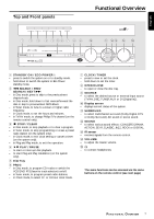
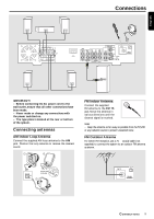
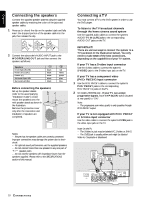
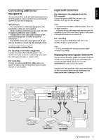
English Connecting the speakers Connect the supplied speaker systems using the supplied speaker cables by matching the colors of the jacks and speaker cables. 1 Press up (or down) the clip on the speaker's jack and fully insert the stripped portion of the speaker cable into the jack, then release the clip. 8 mm a b c 2 Connect the subwoofer's AUDIO INPUT jack to the WOOFER LINE OUT jack and then connect the speakers as follows : Speakers Front Right (R) (FR) Front Left (L) (FL) Center (C) Surround Right (SR) Surround Left (SL) - black black black black black + red white green gray blue Before connecting the speakers; q Set up the speaker stands (refer to the accompanying "Installation Guide") or/and mount the speakers onto the mini speaker stands as shown in the illustration. q Remove the protective cover only after the connection and installation of speakers are completed. Notes: - Ensure that the speaker cables are correctly connected. Improper connections may damage the system due to shortcircuit. - For optimal sound performance, use the supplied speakers. - Do not connect more than one speaker to any one pair of +/- speaker jacks. - Do not connect speakers with impedance lower than the speakers supplied. Please refer to the SPECIFICATIONS section of this manual. Connecting a TV You must connect a TV to the DVD system in order to use the DVD player. To listen to the TV broadcast channels through the home cinema sound system q Use the supplied audio cables to connect the system's AUDIO-TV IN (L/R) jacks to the corresponding AUDIO OUT jacks on the TV. IMPORTANT! There are various ways to connect the system to a TV (as shown in the illustration below). You only need to make ONE of the best connections, depending on the capabilities of your TV system. If your TV has a S-video input connector q Use the S-video cable to connect the system's S-VIDEO jack to the S-Video input jack on the TV. If your TV has a component video (Pr/Cr Pb/Cb Y) input connector 1 Use the Pr/Cr Pb/Cb Y cables to connect the system's Pr/Cr Pb/Cb Y jacks to the corresponding Pr/Cr Pb/Cb Y In jacks on the TV. 2 for model LX8000SA only - If your TV can accept progressive signals, move the P-SCAN switch (located at rear panel) to "ON". Note: - The progressive scan video quality is only possible through Pr/Cr Pb/Cb Y output. If your TV is not equipped with Pr/Cr Pb/Cb Y or S-Video input connector q Use the video cable to connect the system's CVBS jack to the video input jack on the TV. Note: On the TV, - The S-Video In jack may be labeledY/C, S-Video or S-VHS. - The CVBS jack is usually yellow and might be labeled Video In, Composite or Baseband. Pr/Cr Pb/Cb Y + + CDR DIGITAL CENTER AUX OUT OUT IN TV LINE IN OUT DIGITAL WOOFER IN LINE OUT AUDIO VIDEO OUT FM 75 Ω CVBS S-VIDEO Pr/Cr Pb/Cb P-SCAN Y ON OFF AM FM/AM ANTENNA 10 CONNECTIONS
-
 1
1 -
2
-
3
-
4
-
 5
5 -
 6
6 -
 7
7 -
 8
8 -
 9
9 -
 10
10 -
 11
11 -
 12
12 -
 13
13 -
 14
14 -
 15
15 -
16
-
17
-
18
-
19
-
20
-
21
-
22
-
23
-
24
-
25
-
26
-
27
-
28
-
29
-
30
-
31
 |
 |
