Philips RFX6500 Leaflet - Page 2
RFX6500/17
 |
UPC - 037849966556
View all Philips RFX6500 manuals
Add to My Manuals
Save this manual to your list of manuals |
Page 2 highlights
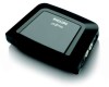
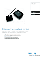
RF extender RFX6500/17 Specifications Connectivity • IR emitter connectors: 4 • Connector: 2.5 mm Blaster- Receiver connector Infrared Capabilities • IR emitter connectors: 4 • Transmitting LEDs: 4 RF Capabilities • Adresses (ID's): 16 • Channels: 4 • Communication: 1-way • Frequency (MHz): 418 Convenience • Error indication Power • Mains power: 120V (+/-10/-15%)/60Hz Dimensions • Master carton quantity: 1 • Master carton weight: 0.84 kg • Product dimension (WxDxH) inch: 4.5" x 3.2" x 1.2" • Product weight (lb): 0.132 • Temperature range (operation): 32°F to 122°F Accessories • AC/DC Adaptor: 12V DC 400mA • Dual IR emitter wires: 4 • Printed User Guide • Product highlights IR extension module An infrared extension module allows you to control traditional infrared equipment over a radio frequency network. Radio frequency A radio technology that allows you to control components not in direct line-of-sight, such as through walls or other obstacles. There are two types of RF used in remote controls: RF to component, and RF to infrared. Adjustable antenna A separate adjustable antenna determines the most reliable position of an RF extender and therefore enables virtually interference-free operation of multi-room systems or devices in concealed environments. The antenna has a built-in interference indicator that blinks when detecting an other RF device or other interference source (e.g. microwave oven). The harder the indicator blinks, the less reliable the position of the antenna. RF interference indicator An interference indicator is a red blinking light that indicates the presence of interference sources in the home, that can interfere with the operation of an RF extender. The indicator is built into an antenna, and starts blinking as soon as the antenna picks up interference from RF devices, besides the RF extender, or other sources e.g microwave oven. The harder the light blinks, the less reliable the antenna is positioned, therefore, the less reliable the RF extender will work. Issue date 2008-01-19 Version: 1.0.6 12 NC: 9082 100 80125 UPC: 0 37849 96655 6 © 2008 Koninklijke Philips Electronics N.V. All Rights reserved. Specifications are subject to change without notice. Trademarks are the property of Koninklijke Philips Electronics N.V. or their respective owners. www.philips.com
-
 1
1 -
 2
2
 |
 |
