Pioneer AVHP5700DVD Other Manual - Page 4
Installation, <ENGLISH> - parts
 |
UPC - 012562734668
View all Pioneer AVHP5700DVD manuals
Add to My Manuals
Save this manual to your list of manuals |
Page 4 highlights
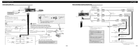
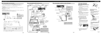
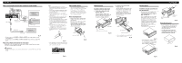
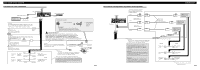
Installation When connecting the external video component and the display Audio input Video input To audio outputs Video output RCA cables (sold separately) To video output External video component (sold separately) Audio output Multi-DVD Player (sold separately) Video output RCA cable (sold separately) To video input Display with RCA input jacks Fig. 11 • It is necessary to set AV INPUT to VIDEO in SET UP when connecting the external video component. • It is necessary to set AV INPUT to M-DVD in SET UP when connecting a multi-DVD player. When using a display connected to rear video output This product's rear video output is for connection of a display to enable passengers in the rear seats to watch the DVD or Video CD. WARNING: • NEVER install the display in a location that enables the Driver to watch the DVD or Video CD while Driving. Note: • Before finally installing the unit, connect the wiring temporarily, making sure it is all connected up properly, and the unit and the system work properly. • Use only the parts included with the unit to ensure proper installation. The use of unauthorized parts can cause malfunctions. • Consult with your nearest dealer if installation requires the drilling of holes or other modifications of the vehicle. • Install the unit where it does not get in the driver's way and cannot injure the passenger if there is a sudden stop, like an emergency stop. • Do not install the display where it may (i) obstruct the driver's vision, (ii) impair the performance of any of the vehicle's operating systems or safety features, including air bags, hazard lamp buttons or (iii) impair the driver's ability to safely operate the vehicle. • The semiconductor laser will be damaged if it overheats, so don't install the unit anywhere hot - for instance, near a heater outlet. • If installation angle exceeds 30° from horizontal, the unit might not give its optimum performance. (Fig. 12) DIN Front/Rear-mount This unit can be properly installed either from "Front" (conventional DIN Front-mount) or "Rear" (DIN Rearmount installation, utilizing threaded screw holes at the sides of unit chassis). For details, refer to the following illustrated installation methods. Before installing the unit • Remove the frame and the holder. (Fig. 14) Pull out to remove the frame and then loosen the screws (2 × 3 mm) to remove the holder. (When reattaching the frame, point the side with a groove downwards and attach it.) 30° Fig. 12 • The cords must not cover up the area shown in the figure below. This is necessary to allow the amplifires to radiate freely. (Fig. 13) Holder Screw (2 × 3 mm) Frame Fig. 14 Do not close this area. Fig. 13 DIN Front-mount Installation with the rubber bush 1. Decide the position of the side brackets. (Fig. 15) When installing in a shallow space, change the position of side brackets. In this case, stick conceal tape on parts that protrude from the dashboard. Conceal tape Side bracket Flush surface screw (5 × 6 mm) Fig. 15 2. Install the unit into the dashboard. (Fig. 16) After inserting the holder into the dashboard, then select the appropriate tabs according to the thickness of the dashboard material and bend them. (Install as firmly as possible using the top and bottom tabs. To secure, bend the tabs 90 degrees.) Dashboard 182 53 Rubber bush Screw Holder Side bracket Screw (2 × 3 mm) • After installing the unit into the dashboard, reattach the frame. Fig. 16 DIN Rear-mount Installation using the screw holes on the side of the unit • Fastening the unit to the factory radio mounting bracket. (Fig. 17) (Fig. 18) (Fig. 19) Select a position where the screw holes of the bracket and the screw holes of this product become aligned (are fitted), and tighten the screws at 2 places on each side. Use any of binding screws (4 × 3 mm), binding screws (5 × 6 mm) or flush surface screws (5 × 6 mm), depending on the shape of the screw holes in the bracket. *1 Use binding screws (4 × 3 mm) only. *1 *1 Screw Factory radio mounting bracket Dashboard or Console Fig. 19 Fixing the front panel If you do not operate the removing and attaching the front panel function, use the supplied fixing screws to fix the front panel to this unit. • Fix the front panel to the unit using fixing screws after removing the front panel. (Fig. 20) Fig. 17 • When installing in a shallow space, use the following screw holes. In this case, stick conceal tape on parts that protrude from the dashboard. Conceal tape *1 *1 Fixing screw Fig. 20 Fig. 18
-
 1
1 -
 2
2 -
 3
3 -
 4
4 -
 5
5 -
 6
6 -
 7
7 -
 8
8
 |
 |
