Pioneer AVIC N4 Other Manual
Pioneer AVIC N4 - Navigation System With DVD player Manual
 |
UPC - 012562863078
View all Pioneer AVIC N4 manuals
Add to My Manuals
Save this manual to your list of manuals |
Pioneer AVIC N4 manual content summary:
- Pioneer AVIC N4 | Other Manual - Page 1
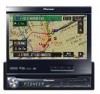
English INSTALLATION MANUAL Français MANUEL D'INSTALLATION AVIC-N4 This product conforms to CEMA cord colors. Le code de couleur des câbles utilisé pour ce produit est conforme à CEMA. - Pioneer AVIC N4 | Other Manual - Page 2
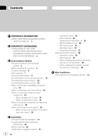
When using a rear display connected to rear video output 20 Installation Precautions before installation 21 To guard against electromagnetic interference 21 Before installing 22 Installing this navigation system 22 2 En - Installation notes 22 - Parts supplied 23 - Installing the hide-away unit 25 - Pioneer AVIC N4 | Other Manual - Page 3
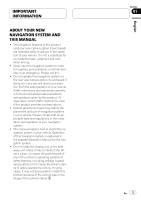
and operation of your navigation system. ! This manual explains how to install this navigation system in your vehicle. Operation of this navigation system is explained in the separate Operation Manual for the navigation system. ! Do not install the display unit or the hideaway unit where it may - Pioneer AVIC N4 | Other Manual - Page 4
belt is not properly buckled. WARNING Do not attempt to install or service your navigation system by yourself. Installation or servicing of the navigation system by persons without training and experience in electronic equipment and automotive accessories may be dangerous and could expose you to the - Pioneer AVIC N4 | Other Manual - Page 5
install your navigation system yourself. We recommend that only authorized Pioneer service personnel, who have special training and experience in mobile electronics, set up and install this product. NEVER SERVICE THIS PRODUCT YOURSELF. Installing or servicing this product and its connecting cables - Pioneer AVIC N4 | Other Manual - Page 6
replacing the fuse, be sure to only use a fuse of the rating prescribed on the fuse holder. - When disconnecting a connector, pull the connector itself. Do not pull the lead, as you may pull it out of the connector. - This product cannot be installed in a vehicle that does not have an ACC (accessory - Pioneer AVIC N4 | Other Manual - Page 7
audio source is switched off. ! When an external power amp is being used with this system, be sure not to connect the blue/white lead to pin cable Extension antenna cable GPS antenna RCA connector Parts supplied The display unit Connector The hide-away unit Extension lead (for reverse signal - Pioneer AVIC N4 | Other Manual - Page 8
-DVD player) Hide-away unit (supplied with XDV-P6) IP-BUS cable (supplied with USB adapter) Black Multi-DVD player (XDV-P6) (sold separately) 25-pin cable (supplied with multi-DVD player) Black To video output (FRONT) RCA cable (sold separately) IP-BUS cable (supplied with Bluetooth adapter - Pioneer AVIC N4 | Other Manual - Page 9
Section 03 English 20 cm (7-7/8 in.) WIRED REMOTE INPUT Please see the Instruction Manual for the Wired Remote Control Adapters (sold separately). The display unit 3 m (9 ft. 10 in.) Black (Extension port) 30-pin cable (supplied) Yellow (VIDEO IN) GPS antenna 5 m (16 ft. 5 in.) Light gray - Pioneer AVIC N4 | Other Manual - Page 10
from this navigation system, the audio volume is automatically muted or attenuated. Subwoofer output or non-fading output (SUBWOOFER OUTPUT or NON-FADING OUTPUT) 20 cm (7-7/8 in.) GUIDE SP OUTPUT Guide speaker (e.g.CD-TS37GP) (sold separately) The display unit Secure the connector using the screw - Pioneer AVIC N4 | Other Manual - Page 11
Blue OPT.IN 2 RCA cable (supplied with multi-channel processor) Optical cable (supplied with multi-channel processor) Multi-channel processor controller unit (e.g. AXM-P8000) (Hide away unit) Blue Multi-channel processor controller unit (e.g. AXM-P8000) (Display unit) English Section 03 En - Pioneer AVIC N4 | Other Manual - Page 12
vehicle (metal) body. Note When a subwoofer is connected to this navigation system instead of a rear speaker, change the rear output setting in the Initial Setting. (Refer to the Operation Manual.) The subwoofer output of this navigation system is monaural. With a 2 speaker system, do not connect - Pioneer AVIC N4 | Other Manual - Page 13
Connecting the System The display unit Power cord Yellow/Black (MUTE) If you use equipment with a mute function, connect that Operation Manual. - voice guidance of the navigation - incoming Ringtone and incoming voice of the cellular phone that is connected to this navigation system via Bluetooth - Pioneer AVIC N4 | Other Manual - Page 14
suggested that the speed pulse wire be connected for accuracy of navigation and better performance of interlock. • If the speed pulse wire is unavailable for some reason, it is recommended that the pulse generator (ND-PG1) be used. WARNING LIGHT GREEN LEAD AT POWER CONNECTOR IS DESIGNED TO DETECT - Pioneer AVIC N4 | Other Manual - Page 15
Pioneer audio unit for the vehicle, if the vehicle stereo has yellow/black leads, connect them to those leads. In this way, the vehicle stereo is automatically muted to reduce the vehicle stereo volume when; - the guidance audio is output. - the mobile phone is used via Bluetooth adapter. Violet - Pioneer AVIC N4 | Other Manual - Page 16
sold power amp Subwoofer output or non-fading output (SUBWOOFER OUTPUT or NONFADING OUTPUT) 20 cm (7-7/8 in.) RCA connector Rear output (REAR OUTPUT) 15 cm (5-7/8 in.) The display unit Front output (FRONT OUTPUT) 15 cm (5-7/8 in.) 30 cm (12 in.) Blue/White To system control terminal of - Pioneer AVIC N4 | Other Manual - Page 17
Perform these connections when using the optional amplifier. RCA cables (sold separately) Power amp (sold separately) Power amp (sold separately) Power amp (sold separately) System remote control Left Front speaker Right Front speaker Rear speaker Rear speaker Subwoofer Subwoofer Note - Pioneer AVIC N4 | Other Manual - Page 18
INPUT ONLY FOR REVERSE OR MIRROR IMAGE REAR VIEW CAMERA. OTHER USE MAY RESULT IN INJURY OR DAMAGE. Rear view camera To video output RCA cable (sold separately) Brown (REAR VIEW CAMERA IN) CAUTION ! The screen image may appear reversed. ! The rear view camera function is to use this product as - Pioneer AVIC N4 | Other Manual - Page 19
The hide-away unit When using the AV-2 Input The hide-away unit Yellow (VIDEO IN) White, Red (AUDIO IN) CD-RM10 (sold separately) Mini jack (AV 2) White, Red Yellow RCA cables (sold separately) RCA cables (sold separately) To video output To audio outputs To video output To audio outputs - Pioneer AVIC N4 | Other Manual - Page 20
output Black To video output Pioneer external unit (sold separately) ! It is necessary to set "AV1 Input" in "System" to "EXT" when connecting the ex- Rear display with RCA input jacks When using a rear display connected to rear video output WARNING NEVER install the rear display in a location - Pioneer AVIC N4 | Other Manual - Page 21
this system in your vehicle. Please comply with all applicable laws and regulations regarding the use, installation and operation of your navigation system. ! Do not install the display unit or the hideaway unit where it may (i) obstruct the driver's vision, (ii) impair the performance of any of the - Pioneer AVIC N4 | Other Manual - Page 22
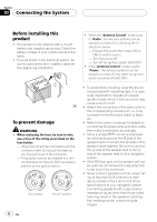
vehicle. ! Before making a final installation of this product, temporarily connect the wiring to confirm that the connections are correct and the system works properly. Installing this navigation system Installation notes ! Do not install the display unit or the hideaway unit in places where it may - Pioneer AVIC N4 | Other Manual - Page 23
if it overheats, so don't install the display unit anywhere hot - for instance, near a heater outlet. ! When installing the hide-away unit in the trunk, use the extension cable (e.g. CDSC300E)(sold separately). ! Do not install the display unit in a position where the opening of the LCD panel is - Pioneer AVIC N4 | Other Manual - Page 24
screw (5 mm × 6 mm) (4 pcs.) Flush surface screw (5 mm × 6 mm) (4 pcs.) Screw (4 mm × 3 mm) (4 pcs.) Fixing screw (2 pcs.) ! Be sure to install the hide-away unit on the floor with the silk printing side is facing up. The navigation system will operate properly only in this position. 24 En - Pioneer AVIC N4 | Other Manual - Page 25
Section 04 English Installing the hide-away unit 1 Attach the side brackets to the hideaway unit. When the hide-away unit is installed on the floor or the installation board under the passenger seat, etc., the side brackets should be attached to the unit. Use the following holes in the - Pioneer AVIC N4 | Other Manual - Page 26
either from "Front" (conventional DIN Frontmount) or "Rear" (DIN Rearmount installation, using threaded screw holes at the sides of unit chassis). For details, refer to the following illustrated installation methods. Before installing the unit % Remove the frame and the holder. Extend top and - Pioneer AVIC N4 | Other Manual - Page 27
conceal tape on parts that protrude from the dashboard. *1 *1 Side bracket Screw (2 mm 3 mm) ! When using the side brackets (large), reat- tach the frame. Conceal tape Binding screw (5 mm 6 mm) DIN Rear-mount Installation using the screw holes on the side of the unit % Fastening the unit to the - Pioneer AVIC N4 | Other Manual - Page 28
not cut the GPS antenna lead to shorten it or use an extension to make it longer. Altering the antenna cable could result in a short circuit or malfunction and permanent damage to the navigation system. Installation notes ! The antenna should be installed on a level surface where radio waves will be - Pioneer AVIC N4 | Other Manual - Page 29
Section 04 English When installing the antenna inside the vehicle (on the rear shelf) Affix the metal sheet on as level a surface as possible where the GPS antenna faces the window. Place the GPS antenna on the metal sheet. (The GPS antenna is fastened with its magnet.) GPS antenna Metal Sheet - Pioneer AVIC N4 | Other Manual - Page 30
Installation When installing the antenna outside the vehicle (on the body) Put the GPS antenna in a position as level as possible, such as on the roof or trunk lid. (The GPS antenna is fastened with a magnet.) GPS the top of the rubber packing. Clamps Use clamps to secure the lead where necessary - Pioneer AVIC N4 | Other Manual - Page 31
the negative (-) cable to the negative (-) terminal of the battery. 2 Start the engine. 3 Press the RESET button. Press the RESET button on the display unit using a pointed object such as the tip of a pen. 4 Enter the following settings: 1 Install the program in the navigation system. 2 Set - Pioneer AVIC N4 | Other Manual - Page 32
à l'installation 52 Installation de ce système de navigation 52 - Remarques sur l'installation 52 - Pièces fournies 54 - Installation de l'unité déportée 56 - Montage DIN avant/arrière 57 - Montage DIN avant 57 - Montage DIN arrière 58 - Fixation du panneau avant 58 Installation de l'antenne GPS 59 - Pioneer AVIC N4 | Other Manual - Page 33
de votre système de navigation. ! Ce manuel vous explique comment installer ce système de navigation dans votre véhicule. Son utilisation proprement dite est expliquée dans le Manuel de fonctionnement du système de navigation. ! N'installez pas l'unité d'affichage ou l'unité déportée à un endroit - Pioneer AVIC N4 | Other Manual - Page 34
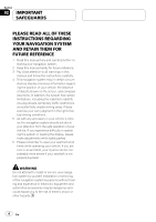
ET LES CONSERVER POUR VOUS Y REFERER PAR LA SUITE 1 Lisez attentivement le contenu du présent manuel avant d'installer votre système de navigation. 2 Conservez ce manuel à portée de main pour vous y référer ultérieurement. 3 Tenez compte de tous les avertissements formulés dans ce manuel et - Pioneer AVIC N4 | Other Manual - Page 35
de service Pioneer agréé, qui a été spécialement formé et est expérimenté en matière de systèmes électroniques mobiles, de montage et d'installation de ce type de produit. NE TENTEZ JAMAIS D'EFFECTUER VOUS-MÊME L'ENTRETIEN OU DE DEPANNER CE SYSTEME DE NAVIGATION. L'installation ou l'entretien - Pioneer AVIC N4 | Other Manual - Page 36
installation. ! Afin d'éviter tout risque de court-circuit, débranchez le câble de la borne négative (-) de la batterie avant de commencer la pose. ! Lorsque le mode "Antenna Control" est réglé sur "Radio", l'antenne du véhicule peut être arrimée ou éteinte en suivant les instructions unit navigation - Pioneer AVIC N4 | Other Manual - Page 37
dans la plage de 4 ohms à 8 ohms caractéristique de votre système de navigation. Si la puissance et/ou l'impédance des hautparleurs branchés sont différentes de celles tout comme un endommagement de l'antenne motorisée du véhicule. L'unité déportée Câble de rallonge (pour signal de marche arriè - Pioneer AVIC N4 | Other Manual - Page 38
combiner ce système de navigation avec le GEX-P10XMT (vendu séparément), cette connexion est nécessaire. - Pour installer le tuner XM dans le coffre, etc., la rallonge (par ex. CD-600DC) (vendu séparément) est nécessaire. Noir Tuner radio satellite SIRIUS compatible avec Pioneer (par ex. SIR-PNR2 - Pioneer AVIC N4 | Other Manual - Page 39
séparément). Noir (Port d'extension) Antenne GPS 5 m L'unité d'affichage 3 m Jaune (VIDEO IN) Câble 30 broches (fourni) L'unité déportée Gris clair Bleu 3 m Cordon-rallonge de câble d'antenne (fourni) Antenne du véhicule Jack Antenne iPod® avec Connecteur de fixation Port du connecteur de - Pioneer AVIC N4 | Other Manual - Page 40
23 cm Jaune/Noir (GUIDE ON) Pour combiner le système de navigation avec le processeur multi-canal, branchez ce câble au câble jaune/noir de l'unité de contrôleur du processeur multi-canal. Ainsi, lorsque le système de navigation émet un signal de sourdine, le volume audio est automatiquement att - Pioneer AVIC N4 | Other Manual - Page 41
ément) OPT.IN 2 Bleu Câble à fiches Cinch (RCA) (fourni avec le processeur multi-canal) Câble optique (fourni avec le processeur multi-canal) Unité de contrôleur de processeur multi-canal (par ex. AXM-P8000) (Unité déportée) Bleu Unité de contrôleur de processeur multi-canal (par ex. AXM-P8000 - Pioneer AVIC N4 | Other Manual - Page 42
La sortie pour haut-parleur d'extrêmes-graves du système de navigation est monaurale. Haut-parleur avant Gauche Haut-parleur arrière ou Haut- Vert/Noir Dans le cas d'une installation comportant 2 hautparleurs, ne reliez rien d'autre que les haut-parleurs aux cordons de liaison. Gris Gris/Noir - Pioneer AVIC N4 | Other Manual - Page 43
Branchement du système L'unité d'affichage Cordon d'alimentation Jaune/Noir (MUTE) Si vous utilisez un du téléphone portable qui est connecté à ce système de navigation via la technologie sans fil Bluetooth Remarque L'antenne se rétracte ou s'éteint automatiquement, mais la temporisation - Pioneer AVIC N4 | Other Manual - Page 44
unité déportée 5 m Fermez le couvercle. Câble de rallonge (pour signal de vitesse) Rose (CAR SPEED SIGNAL INPUT) Remarque Le système de navigation véhicule. Pour plus de détails, consultez votre revendeur Pioneer agréé ou un installateur professionnel. AVERTISSEMENT UNE CONNEXION INAPPROPRIEE - Pioneer AVIC N4 | Other Manual - Page 45
és a ces fils conducteurs. De cette maniere, l'installation stéréo du véhicule est automatiquement mise en sourdine et son volume est atténué quand : - le guidage sonore est en service. - le téléphone portable est utilisé via l'adaptateur Bluetooth. Violet/Blanc (REVERSEGEAR SIGNAL INPUT) Cette - Pioneer AVIC N4 | Other Manual - Page 46
-parleur d'extrêmes graves ou sortie sans atténuation (SUBWOOFER OUTPUT or NON-FADING OUTPUT) 20 cm Connecteur RCA Sortie arrière (REAR OUTPUT) 15 cm L'unité d'affichage Sortie avant (FRONT OUTPUT) 15 cm 30 cm Bleu/Blanc A la borne de commande d'ensemble de l'amplificateur de puissance (max. 300 - Pioneer AVIC N4 | Other Manual - Page 47
Branchement du système Section 03 Français Effectuez ces connexions si l'amplificateur en option est utilisé. Câble à fiches Cinch (RCA) (vendu séparément) Amplificateur de puissance (vendu séparément) Amplificateur de puissance (vendu séparément) Amplificateur de puissance (vendu séparément) - Pioneer AVIC N4 | Other Manual - Page 48
automatiquement en vidéo lorsque le levier de vitesse est placé en position REVERSE (R). Le mode Vue arrière vous permet également de contrôler en Câble à fiches Cinch (RCA) (vendu séparément) Marron (REAR VIEW CAMERA IN) L'unité déportée Violet/Blanc ATTENTION ! L'image de l'écran peut apparaî - Pioneer AVIC N4 | Other Manual - Page 49
é déportée L'unité déportée Jaune (VIDEO IN) Blanc, Rouge (AUDIO IN) Mini jack (AV 2) Blanc, Rouge CD-RM10 (vendu séparément) Jaune Câble à fiches Cinch (RCA) (vendu séparément) A la sortie vidéo Câble à fiches Cinch (RCA) (vendu séparément) Aux sorties audio Composant vidéo externe (vendu - Pioneer AVIC N4 | Other Manual - Page 50
Aux entrées audio Affichage arrière avec jacks d'entrée RCA Jaune (VIDEO IN) Câble IP-BUS (vendu séparément) Câble à fiches Cinch (RCA) (vendu A la sortie IP-BUS Noir séparément) A la sortie vidéo Unité externe Pioneer vidéo arrière AVERTISSEMENT NE JAMAIS installer l'écran arrière à un - Pioneer AVIC N4 | Other Manual - Page 51
navigation car ces travaux comportent des risques d'électrocution et d'autres dangers. Confiez l'installation et l'entretien à un personnel de service Pioneer qualifié. ATTENTION ! Ne jamais installer le véhicule en toute sécurité. ! Installez l'unité d'affichage entre le siège conducteur et le - Pioneer AVIC N4 | Other Manual - Page 52
système de navigation, d'autres câbles ou de cordons : ! Antenne TV et cordon d'antenne ! Antenne FM, AM et son cordon ! Antenne GPS et son cordon fonctionne normalement. Installation de ce système de navigation Remarques sur l'installation ! N'installez pas l'unité d'affichage ou l'unité déportée - Pioneer AVIC N4 | Other Manual - Page 53
par rapport au sens de déplacement de votre véhicule). Un défaut d'installation de l'unité avec une inclinaison de la surface supérieure à cette marge de tol par les amplificateurs et le mécanisme de navigation puissent se dissiper. L'unité d'affichage Tableau de bord Laissez un espace Panneau LCD Ne pas - Pioneer AVIC N4 | Other Manual - Page 54
Les pièces indiquées par un astérisque (*) sont préinstallées. L'unité déportée L'unité d'affichage Bague de caoutchouc Vis de pression (5 mm × 6 mm) (4 pièces) Vis à tête plate (5 mm × 6 mm) (4 pièces) Vis (4 mm × 3 mm) (4 pièces) Support* Vis à collerette (4 mm × 8 mm) (4 pièces) Cadre - Pioneer AVIC N4 | Other Manual - Page 55
Installation ! Veillez à installer l'unité déportée sur le sol, le côté sérigraphié vers le haut. Le système de navigation ne fonctionnera correctement que dans cette position. Section 04 Français Fr 55 - Pioneer AVIC N4 | Other Manual - Page 56
Section 04 Installation Installation de l'unité déportée 1 Fixez les supports latéraux sur l'unité déportée. Lorsque l'unité déportée est installée sur le plancher ou le panneau d'installation sous le siège passager, etc., les supports latéraux doivent être fixés à l'unité. Utilisez les trous - Pioneer AVIC N4 | Other Manual - Page 57
de montage par "l'arrière" (montage DIN arrière faisant appel aux perçages filetés de chaque côté du châssis). Pour les détails, reportez-vous aux méthodes d'installation illustrées suivantes. Avant d'installer l'unité % Retirez le cadre et le support. Étirez le haut et le bas de le cadre vers l'ext - Pioneer AVIC N4 | Other Manual - Page 58
du tableau de bord. *1 *1 Ruban adhésif de masquage Vis de pression (5 mm 6 mm) Montage DIN arrière Installation en utilisant les trous de vis sur les côtés de l'unité % Fixation de l'unité au support pour le montage d'autoradio usine. Choisir la position selon laquelle les orifices de vis du - Pioneer AVIC N4 | Other Manual - Page 59
un courtcircuit ou un dysfonctionnement et d'endommager définitivement le système de navigation. Remarques sur l'installation ! L'antenne doit être installée sur une surface plane bien réceptive aux ondes radio. Les ondes radio ne peuvent pas être captées correctement par l'antenne si la réception - Pioneer AVIC N4 | Other Manual - Page 60
04 Installation Installation de l'antenne à l'intérieur du véhicule (sur la tablette arrière) Fixez la plaque métallique sur une surface aussi plate que possible située de manière à ce que l'antenne GPS soit orientée vers une vitre. Posez l'antenne GPS sur la plaque métallique. (L'antenne GPS est - Pioneer AVIC N4 | Other Manual - Page 61
Installation Installation de l'antenne à l'extérieur du véhicule (sur la carrosserie) Posez l'antenne GPS sur une surface aussi plate que possible, telle que le toit ou le capot du coffre. (L'antenne GPS est immobilisée par son propre aimant.) Antenne GPS le fil conducteur aux endroits nécessaires - Pioneer AVIC N4 | Other Manual - Page 62
sur la touche RESET de l'unité d'affichage. 4 Faites les réglages suivants: 1 Installez le programme dans le système de navigation. 2 Réglez l'heure et la sur la configuration de votre système de navigation. Remarque Une fois l'installation terminée, vérifiez le bon fonctionnement du véhicule - Pioneer AVIC N4 | Other Manual - Page 63
1, B-9120 Melsele, Belgium TEL: (0) 3/570.05.11 Published by Pioneer Corporation. Copyright © 2007 by Pioneer Corporation. All rights reserved. Publié par Pioneer Corporation. Copyright © 2007 par Pioneer Corporation. Tous droits réservés. Printed in China Imprimé en Chine
-
 1
1 -
 2
2 -
 3
3 -
 4
4 -
 5
5 -
 6
6 -
 7
7 -
8
-
9
-
10
-
11
-
12
-
13
-
14
-
15
-
16
-
17
-
18
-
19
-
20
-
21
-
22
-
23
-
24
-
25
-
26
-
27
-
28
-
29
-
30
-
31
-
32
-
33
-
34
-
35
-
36
-
37
-
38
-
39
-
40
-
41
-
42
-
43
-
44
-
45
-
46
-
47
-
48
-
49
-
50
-
51
-
52
-
53
-
54
-
55
-
56
-
57
-
58
-
59
-
60
-
61
-
62
-
63
 |
 |

MANUEL D’INSTALLATION
INSTALLATION MANUAL
AVIC-N4
This product conforms to CEMA cord colors.
Le code de couleur des câbles utilisé pour ce produit
est conforme à CEMA.
English
Français