Pioneer DEH-P300 Service Manual - Page 54
Checking The Grating After Changing The Pickup Unit
 |
View all Pioneer DEH-P300 manuals
Add to My Manuals
Save this manual to your list of manuals |
Page 54 highlights
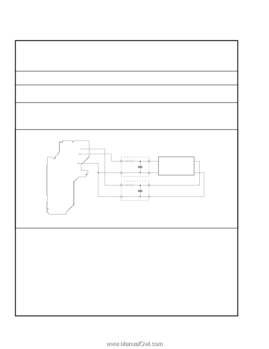
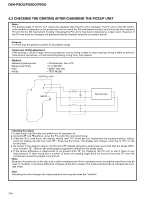
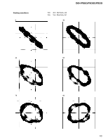
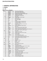
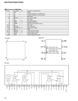
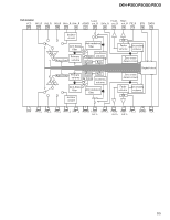
DEH-P300,P3000,P200 6.2 CHECKING THE GRATING AFTER CHANGING THE PICKUP UNIT • Note : The grating angle of the PU unit cannot be adjusted after the PU unit is changed. The PU unit in the CD mechanism module is adjusted on the production line to match the CD mechanism module and is thus the best adjusted PU unit for the CD mechanism module. Changing the PU unit is thus best considered as a last resort. However, if the PU unit must be changed, the grating should be checked using the procedure below. • Purpose : To check that the grating is within an acceptable range. • Symptoms of Mal-adjustment : If the grating is off by a large amount symptoms such as being unable to close tracking, being unable to perform track search operations, or track searching taking a long time, may appear. • Method : • Measuring Equipment • Measuring Points • Disc • Mode • Oscilloscope, Two L.P.F. • E, F, REFOUT • ABEX TCD-784 • TEST MODE CONTROL UNIT F E REFO L.P.F. E REFO 100kΩ 390pF Xch Ych Oscilloscope F REFO 100kΩ 390pF L.P.F. • Checking Procedure 1. In test mode, load the disc and switch the 5V regulator on. 2. Using the ] and [ buttons, move the PU unit to the innermost track. 3. Press key 3 to close focus, the display should read "91". Press key 2 to implement the tracking balance adjust- ment the display should now read "81". Press key 3 2 times. The display will change, returning to "81" on the fourth press. 4. As shown in the diagram above, monitor the LPF outputs using the oscilloscope and check that the phase difference is within 75° . Refer to the photographs supplied to determine the phase angle. 5. If the phase difference is determined to be greater than 75° try changing the PU unit to see if there is any improvement. If, after trying this a number of times, the grating angle does not become less than 75° then the mechanism should be judged to be at fault. • Note Because of eccentricity in the disc and a slight misalignment of the clamping center the grating waveform may be seen to "wobble" ( the phase difference changes as the disc rotates). The angle specified above indicates the average angle. • Hint Reloading the disc changes the clamp position and may decrease the "wobble". 54
-
 1
1 -
2
-
3
-
4
-
5
-
6
-
7
-
8
-
9
-
10
-
11
-
12
-
13
-
14
-
15
-
16
-
17
-
18
-
19
-
20
-
21
-
22
-
23
-
24
-
25
-
26
-
27
-
28
-
29
-
30
-
31
-
32
-
33
-
34
-
35
-
36
-
37
-
38
-
39
-
40
-
41
-
42
-
43
-
44
-
45
-
46
-
47
-
48
-
 49
49 -
 50
50 -
 51
51 -
 52
52 -
 53
53 -
 54
54 -
 55
55 -
 56
56 -
 57
57 -
 58
58 -
 59
59 -
60
-
61
-
62
-
63
-
64
-
65
-
66
-
67
-
68
-
69
-
70
-
71
-
72
-
73
-
74
-
75
-
76
-
77
-
78
-
79
-
80
-
81
-
82
-
83
 |
 |