Pioneer DEH-P700BT Other Manual - Page 2
Connecting the unit, English - wiring
 |
UPC - 012562886213
View all Pioneer DEH-P700BT manuals
Add to My Manuals
Save this manual to your list of manuals |
Page 2 highlights
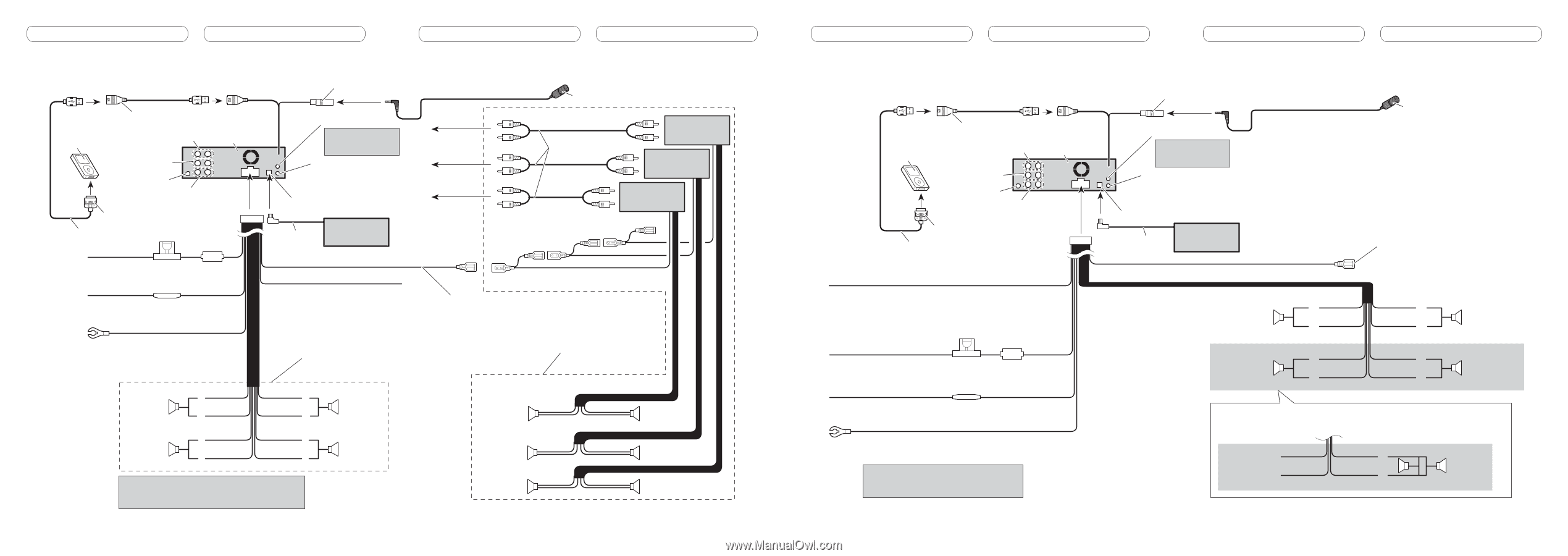
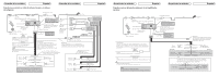
Connecting the unit English When not connecting a rear speaker lead to a subwoofer 1.5 m (4 ft. 9 in.) 20 cm (7-7/8 in.) Microphone input 50 cm (20 in.) iPod USB cable Connect to separately sold USB device. Rear output This product 15 cm (5-7/8 in.) AUX jack (3.5 φ) Use a stereo mini plug cable to connect with auxiliary device. Front output Antenna jack Subwoofer output Wired remote input Hard-wired remote control adaptor can be connected (sold separately). IP-BUS input (Blue) Dock connector Interface cable Fuse (10 A) Multi-CD player IP-BUS cable (sold separately) Connecting the unit English 4 m (13 ft. 1 in.) To rear output To front output To subwoofer output Microphone Connect with RCA cables (sold separately) Power amp (sold separately) Power amp (sold separately) Power amp (sold separately) Yellow Connect to the constant 12 V supply terminal. Fuse resister Red Connect to terminal controlled by ignition switch (12 V DC). Yellow/black If you use an equipment with Mute function, wire this lead to the Audio Mute lead on that equipment. If not, keep the Audio Mute lead free of any connections. Black (chassis ground) Connect to a clean, paint-free metal location. Front speaker Left Rear speaker White White/black Green Green/black With a 2 speaker system, do not connect anything to the speaker leads that are not connected to speakers. Gray Gray/black Violet Violet/black Front speaker Right Rear speaker When connecting speakers without using the internal amplifier, we recommend that this unit's internal amp is turned off. For more details, refer to operation manual. System remote control Blue/white Connect to system control terminal of the power amp or auto-antenna relay control terminal (max. 300 mA 12 V DC). Perform these connections when using the optional amplifier. Subwoofer Front speaker Rear speaker Subwoofer Front speaker Rear speaker Connecting the unit English When using a subwoofer without using the optional amplifier Connecting the unit English 1.5 m (4 ft. 9 in.) 20 cm (7-7/8 in.) Microphone input 50 cm (20 in.) iPod USB cable Connect to separately sold USB device. Rear output This product 15 cm (5-7/8 in.) AUX jack (3.5 φ) Use a stereo mini plug cable to connect with auxiliary device. Front output Antenna jack Subwoofer output Wired remote input Hard-wired remote control adaptor can be connected (sold separately). IP-BUS input (Blue) Dock connector Interface cable Multi-CD player IP-BUS cable (sold separately) 4 m (13 ft. 1 in.) Microphone Blue/white Connect to system control terminal of the power amp or auto-antenna relay control terminal (max. 300 mA 12 V DC). Yellow/black If you use an equipment with Mute function, wire this lead to the Audio Mute lead on that equipment. If not, keep the Audio Mute lead free of any connections. Fuse (10 A) Front speaker Left White Gray White/black Gray/black Front speaker Right Yellow Connect to the constant 12 V supply terminal. Fuse resister Subwoofer (4 Ω) Green Violet Green/black Violet/black Subwoofer (4 Ω) Red Connect to terminal controlled by ignition switch (12 V DC). When using a subwoofer of 70 W (2 Ω), be sure to connect with Violet and Violet/black leads of this unit. Do not connect anything with Green and Green/black leads. Black (chassis ground) Connect to a clean, paint-free metal location. Note: Change the initial setting of this unit. The subwoofer output of this unit is monaural. Not used. Green Green/black Violet Violet/black Subwoofer (4 Ω) 2
-
 1
1 -
 2
2 -
 3
3 -
 4
4 -
 5
5 -
 6
6 -
 7
7
 |
 |